CHAPTER 5: SETTINGS
469 MOTOR MANAGEMENT RELAY – INSTRUCTION MANUAL 5–49
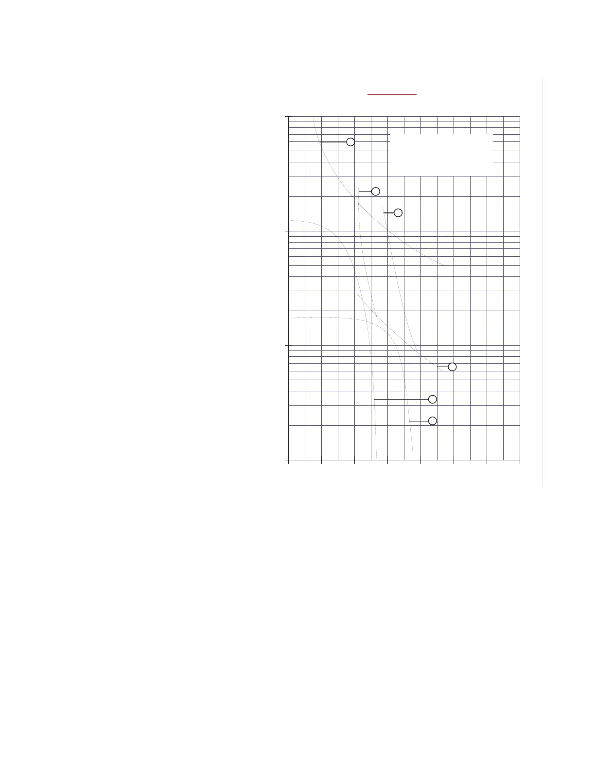
FIGURE 5–8: Thermal Limits for High Inertial Load
To illustrate the Voltage Dependent Overload Curve feature, the thermal limits of FIGURE
5–8: Thermal Limits for High Inertial Load will be used.
1. Construct a custom curve for the running overload thermal limit. If the curve
does not extend to the acceleration thermal limits, extend it such that the curve
intersects the acceleration thermal limit curves (see the Custom Curve below).
2. Enter the per unit current value for the acceleration overload curve intersect
with the custom curve for 80% line voltage. Also enter the per unit current and
safe stall protection time for 80% line voltage (see the Acceleration Curves
below).
3. Enter the per unit current value for the acceleration overload curve intersect
with the custom curve for 100% line voltage. Also enter the per unit current and
safe stall protection time for 100% line voltage (see the Acceleration Curves
below).
1
1
2
3
4
5
6
7
8
2
3
4
5
6
7
8
9
10
20
30
40
50
60
70
80
90
100
HIGH INERTIA LOAD OVERLOAD CUR
VES
8800 HP, 13.2 kV, REACTOR COOLANT PUMP
GE Multilin
TIME TO TRIP (SECONDS)
MULTIPLES OF FULL LOAD AMPS
200
300
400
500
600
700
800
900
1000
1
2
3
4
6
5
1- Running Overload Thermal Limit
2- Acceleration Thermal Limit @ 80%V
3- Acceleration Thermal Limit @ 100%V
4- Locked Rotor Thermal Limit
5- Motor Acceleration Curve @ 80% V
6- Motor Acceleration Curve @ 100%V
806821A4.CDR
g