CHAPTER 6: ACTUAL VALUES
469 MOTOR MANAGEMENT RELAY – INSTRUCTION MANUAL 6–17
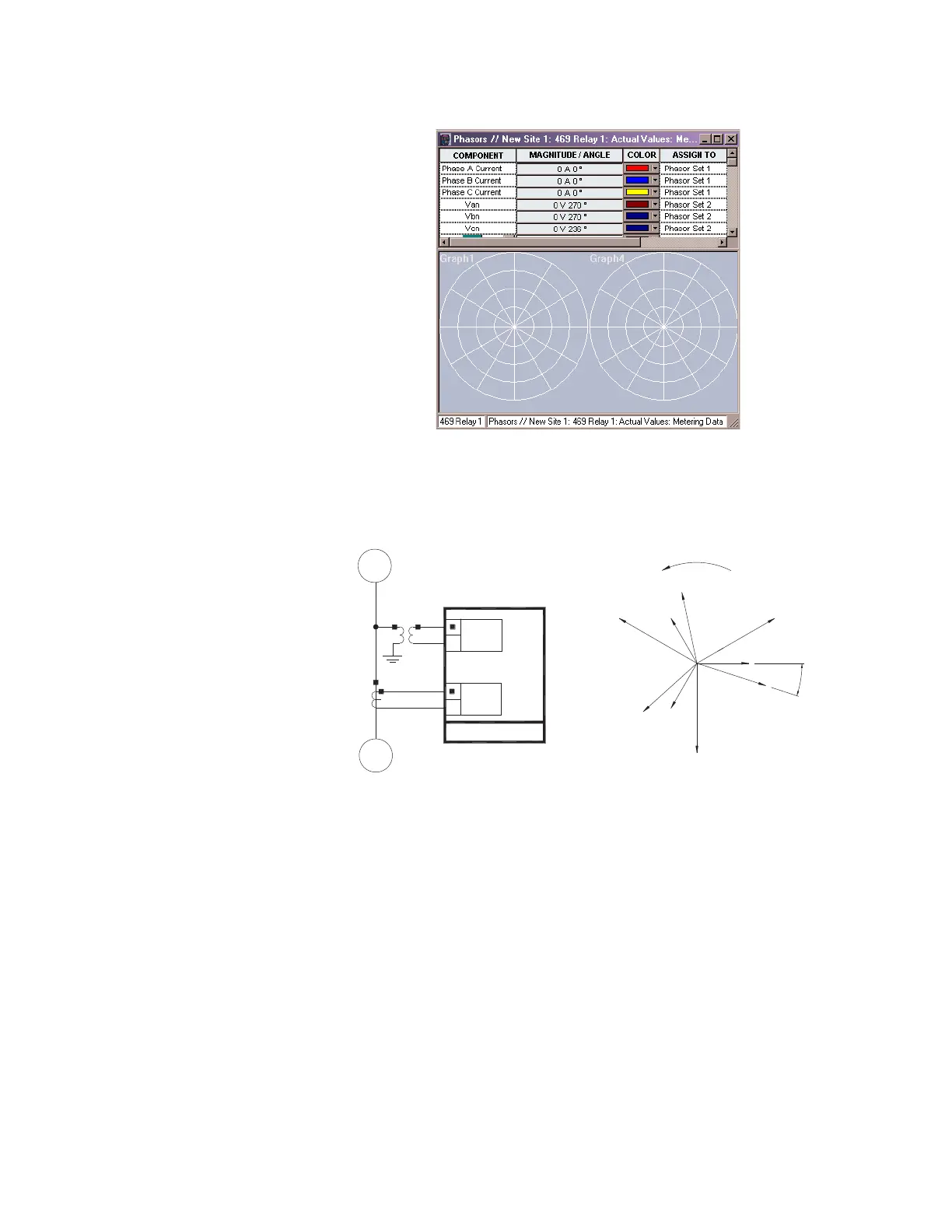
FIGURE 6–1: Vector display in EnerVista 469 Setup
IEEE conventions define vectors in terms of relative angles as shown below:
FIGURE 6–2: Flow Direction of Signed Values for Watts and Vars
All phasors calculated by 469 relays are rotating phasors that maintain the correct phase
angle relationships with each other at all times.
For display purposes, all phasor angles in a given relay are referred to phase Van or Vab,
depending on the
S2 SYSTEM SETUP ZV VOLTAGE SENSING Z VT CONNECTION TYPE settings.
If set to “Wye”, the reference quantity is Van; if set to “Open Delta”, the reference quantity is
Vab. If neither voltage is available, the relay uses the current in Phase A as reference.
The phase angles are assigned and displayed as positive angles. However, by design, the
relay will always work with angles in the lagging direction. This is illustrated below.
806558A1.CDR
Ia
Van
Phase Rotation
Vab
Vcn
Vbn
Ic
Vca
Ib
Vbc
469 Relay
Voltage
Current
WATTS = Positive
VARS = Positive
PF=Lag
M
G
Source
Load
F
° La
g
PER IEEE CONVENTIONS
PARAMETERS ASSEEN
BY THE 469 RELAY