CHAPTER 7: TESTING
469 MOTOR MANAGEMENT RELAY – INSTRUCTION MANUAL 7–9
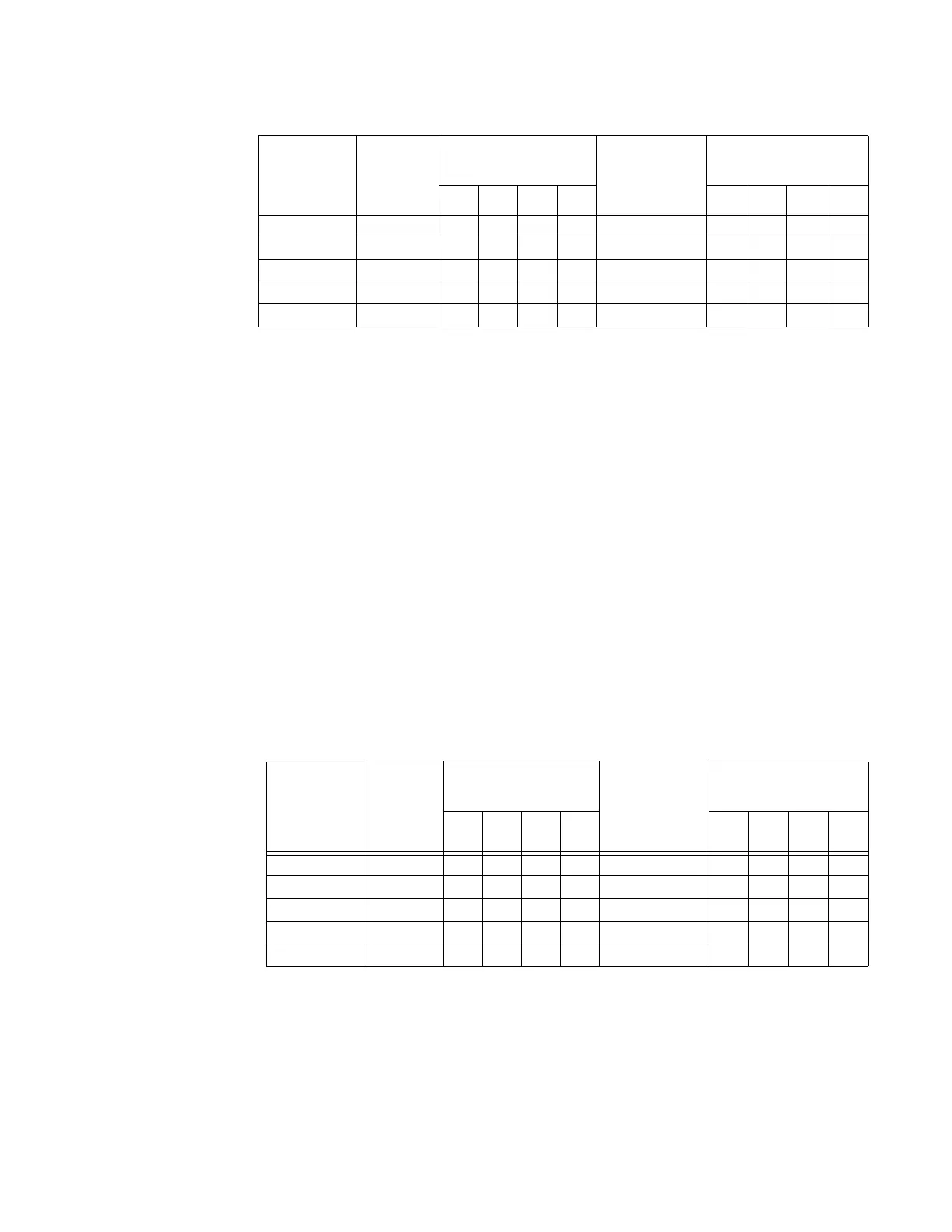
A2 METERING DATA ZV ANALOG INPUTS:
0 to 1 mA Analog Input
Z Alter the following settings:
S12 ANALOG I/O ZV ANALOG INPUT1 Z ANALOG INPUT1: “0-1 mA”
S12 ANALOG I/O ZV ANALOG INPUT1 ZV ANALOG INPUT1 MINIMUM: “0”
S12 ANALOG I/O ZV ANALOG INPUT1 ZV ANALOG INPUT1 MAXIMUM: “1000” (repeat for
Analog Inputs 2 to 4)
Analog output values should be ±0.01 mA on the ammeter. Measured analog input
values should be ±10 units.
Z Force the analog outputs using the following settings:
S13 TESTING ZV TEST ANALOG OUTPUT Z FORCE ANALOG OUTPUTS FUNCTION:
“Enabled”
S13 TESTING ZV TEST ANALOG OUTPUT ZV ANALOG OUTPUT 1 FORCED VALUE: “0%”
(enter desired percent, repeats for analog output 2-4)
Z Verify the ammeter readings as well as the measured analog input
readings.
Z View the measured values in:
A2 METERING DATA ZV ANALOG INPUTS:
ANALOG
OUTPUT
FORCE
VA L U E
EXPECTE
D
AMMETE
R
READING
MEASURED
AMMETER READING
(mA)
EXPECTED
ANALOG
INPUT
READING
MEASURED ANALOG
INPUT READING
(units)
1234 12 34
0% 4 mA 0 mA
25% 8 mA 250 mA
50% 12 mA 500 mA
75% 16 mA 750 mA
100% 20 mA 1000 mA
ANALOG
OUTPUT
FORCE
VA L U E
EXPECT
ED
AMMETE
R
READIN
G
MEASURED
AMMETER
READING (mA)
EXPECTED
ANALOG
INPUT
READING
MEASURED ANALOG
INPUT READING
(units)
1234 1234
0% 0 mA 0 mA
25% 0.25 mA 250 mA
50% 0.50 mA 500 mA
75% 0.75 mA 750 mA
100% 1.00 mA 1000 mA