1–24 469 MOTOR MANAGEMENT RELAY – INSTRUCTION MANUAL
CHAPTER 1: GETTING STARTED
• Motor Operating Curves
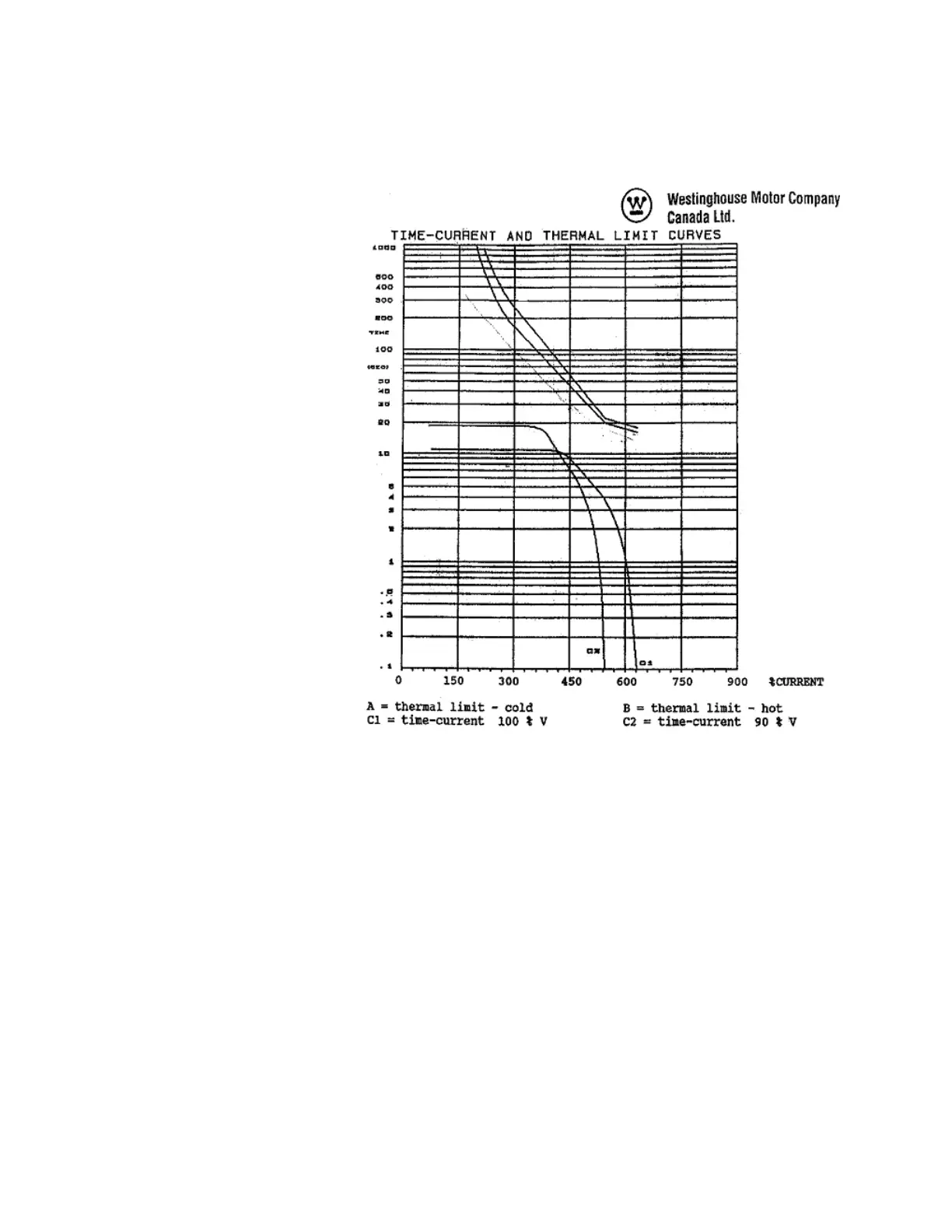
Motor operating curves as shown below:
FIGURE 1–7: Motor Operating Curves for Application Example
• Control System Requirements
– All protection elements trip the breaker
– Breaker position monitoring via 52b contact only
– Only current metering is required
– Serial communication remote start from RTU
– Alarm after 100 s delay from station monitor. This is normally used to signal the
remote center when someone has gained access to the substation.
• Contact Outputs
– Trip and close to breaker control circuit (Trip and Auxiliary2 relays)
– Relay failure alarm to RTU (self-test warning relay, no programming required)
– Alarm contact (setup in General Sw. A for “Station Monitor”)
– No data communications to other equipment.