GEK-7303 Low Voltage
Power
Circuit
Breakers
reduction unit and through a worm
gear
and a
planetary
g~ar
train
drives
the
crank
(10, Fig. 10)
with a reduction 1000:1. To remove the
motor
and gear-reduction unit, _
proceed
as
follows:
1 • . Remove the
front
frame
(see
SEPARATION
OF FRONT
AND
R~AR FRAME.)
2.
.Remove closing
springs
and
crank-shaft
as
illustrate~ iii Fig.-
12
and 13.
3. Disconnect the
leads
from
motor and remove
the -wires attached to
gear
unit housing.
4.
Remove four bolts
at
the bottom of the
front
frame
and one
bolt
at
top of
gear
reduction
unit. The.
motor
and
gear
unit may
n!JW
be removed .•
NOTE
:
If
it
is
desired
to
replace
only the
motor unit, disconnect the
motor
. leads - and
remove only the hardware fastening
it
to the
. - -gear-reduction unit. When removing the motor
· only, the front
frame
should be placed
front
· side
down
to prevenJ. the oil escaping from the
. ·
gear
unit. ·
The
gear
. reduction
unit
contains 4 ounces of
oil
similar
to Atlantic Refining Company's Grade
HFS
No.
3.
·n
should not be
necessary
to add
or
· change oil except when the gear'.'.'reduction
unit-and
motor
are
disassembled • . - ·
QUICK
CLOSE
BREAKER
· .
ADJUSTMENTS
.
The quick close
breaker
basically differs
from
the standard
breaker
in
that
~e
p~echarging
_ operati<;m
is
extended
to
and slightly
past
the top
dead-
center
position of the closing
spring
assembly.
As
_.!tie
springs
start
. to discharge~ to close the
bre_aker, the discharge operation
is
arrested
by
~
pi:ap
and latch arrangement. The subsequent
closing operation
is
accomplished · by tripping
the
-latch to
release
the
prop
which in
turn
allows
the springs
to
continue the interrupted discharging
operation and close the
breaker.
The
gear
reduction unit
for
the
standard
breaker
is
· not interchangeable with the
gear
reduction
uniLon the quick
close
unit because the quick
close
gear
reduction unit employs a
slip
clutch
to relieve the
pressure
that would otherwise
be
. exerted between the output
crank
plate and
the prop. . ·
After the· closing springs have been completely
charged and the prop and latch
system
are
pre-
venting
closure
of
the
breaker,
the closing
opera-
tion may
be
.accomplished by energizing the closing
relay.
thni
the control relay contacts,
or
man-
ually- by
depressing
the push to
close
lever
which
mechanically displaces the latch to allow the
break~r to
close.
· .
. . .
On
drawout
breakers
an interlock between the ··
breaker and enclosure
requires
the springs
to
be
discharged before the
breaker
can be removed
from the
enclosure.
16
.
.'
'c"
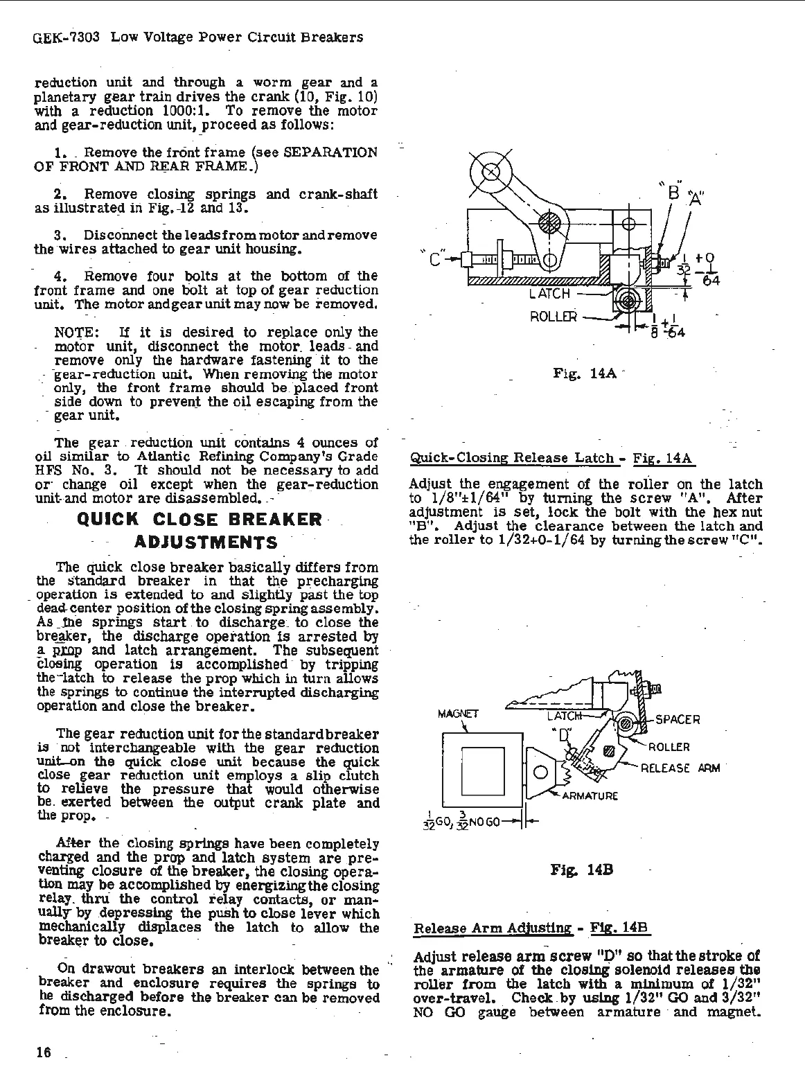
Fig
. 14A ·
Quick-Closing
Release
Latch
-
Fig.
14A
Adjust the engagement of the
roiler
on the
latch
to 1/8
11
±1/64" by
turning
the
screw
"A".
After
adjustment
is
set,
lock
the
bolt
with the hex nut
"B". Adjust the
clearance
between the
latch
and
the
roller
to
1/32+0-1/64
by
turning
the
screw
"C".
D
Fig. 14B
Release Arm Adjusting -
Fig.
l4B
Adjust release arm screw
"P"
so that
the
stroke of
the
armature
of the closing
solen<:>id
releases
the
roller
from
the
latch
with a minimum
of
1/32"
over-travel.
·Check. by
using
1/32"
GO
and
3/32"
NO
·
GO
gauge between
armature
· and magnet.

 Loading...


