GEK-7303 Low Voltage Power
Circuit
Breakers
6 5 4 3 2
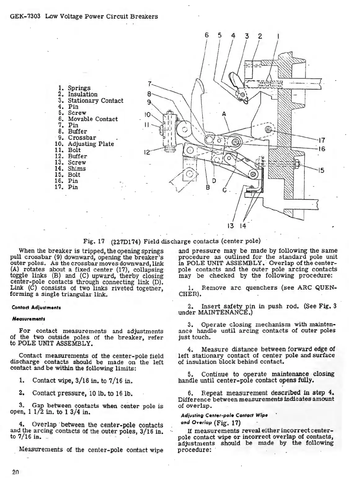
1. Springs
2. Insulation
3.
Stationary Contact
4.
Pin
.
5. Screw
6. Movable Contact
7.
Pin
8. Buffer
· 9 •.
Crossbar
10. Adjusting
Plate
11. Bolt
12. Buffer
13. Screw
14. Shims
15. Bolt
16. Pin
17. Pin
13
14
Fig.
17
(227Dl 74) Field discharge c~ntacts
(center
pole)
When
the
breaker
is
tripped, the opening springs
pull
crossbar
(9) downward, opening the
breaker's
outer poles. As the
crossbar
moves downward, link
(A)
rotates
about a fixed
center
(17)",
collapsing
toggle links
(B)
and
(C)
upward, therby closing
center-pole contacts through connecting
link
(D).
Link
(C)
consists
of
two
links
riveted
together,
forming a single
triangular
· link.
Contact Adjustments
Measurements
For
contact measurements and adjustments
of the two outside poles of the
breaker,
refer
to POLE
UNIT
ASSEMBLY.
Contact measurements of the
center-pole
field
discharge contacts should be made on the left
contact and be
within
the
following
limits:
1. Contact wipe, 3/16 in. to
7/16
in.
2. Contact
pressure,
·
10
lb. to
16
lb.
3.
Ga_p
between contacts when
center
pole
is
open, 1
1/2
in.
to
1
3/4
in.
4. Overlap · between the center-pole contacts
and the
arcing
contacts of the
outer
poles, 3/16 in
··
to 7/16 in. _ · •
Measurements of the center-pole contact wipe
20
and
pressure
may be made by following the
same
procedure
as
outlined
for
the
standard
pole unit
in POLE UNIT ASSEMBLY:· Overlap
of
the
center-
pole contacts and the
outer
pole
arcing
contacts
may be checked by the following
procedure:
. - .
1. Remove
arc
quenchers
(see
ARC QUEN-
CHER). · . .
2.
Insert
safety
pin
in
push
rod.
(See Fig. 3
under MAINTENANCE.)
3.
Operate
closing me~hanism with mainten-
ance handle until
arcing
contacts
of
outer
poles
just
touch.
4.
Measure
distance
between forward edge of
left
stationary
contact of
center
pole and surface
of insulation block behind contact.
5.
Continue to
operate
maintenance closing
handle
until
center-pole
contact opens fully.
6.
Repeat
measurement
described in
step
4.
Difference between measurements indicates amount
of
overlap.
Adjusting
Center-pole
Contact
Wipe
and
Overlap
·{Fig. 17)
If
measurements
reveal
either
incorrect
center-
pole contact wipe
or
incorrect
overlap of confacts,
adjustments
should be made by the following
procedure:

 Loading...


