3.
On drawout
breakers
wired
for
the fourth
gr
·ound
sensor
coil, unsolder
external
sensor
coil
leads
at
terminal
board
on
female
disconnect
plug. On
stationary
b
reak
e
rs
unsolder
twisted
shielded
pair
from
Terminal
Board
(Fi
g.
40).
4~
Remove the
four
bolts
connecting each
· coil as·sembly to the pole unit.
5. Remove the coil
assemblies
taking
care
not to damage the inter-connecting coil
wires.
· 6.
No
further
breakdown of the .coil
assem
-
blies
should
be
made. Do not
re
move the coils
from
around
their
iron
core
.
7.
· Replace coil
assemb
lies
in
revers
e
orde
r.
Sensor
Coils (Al_{-3-75/100) Only (Fig. 33)
1. Disconnect control plug between Power
Supply Unit and
Sensor
Coils.
2.
If
present,
disconnect fourth ground sensor
coil lead
as
described
in
Step 3 above.
3. Di
sconnect
·
resistor
board
from
back
frame
by removing two nuts
from
studs welded
to
back
frame.
Remove the two remaining hex head
bolts and
nuts.
Lift
board
from
the two
studs.
·
4.
Remove
collar
at
end of
primary
dis-
connects by loosening two allen head bolts and
sliding off
collar.
.~
100
0
I J J
11
I I
_I
I I
N.ONO•TIU
DELAY
Pffl~'i'!.:A0..USW11..E
0
,
,Oa,.
Tri
,.,.__.
_11
.
!!JlN~
so
200
10
0
0
~--
0
~
MAXNUM BREA!(£"
~i:::~
:,.:I''
0..£AIING•TIME
0
,
....
.....
':
~
.....
l'~
0
TI
ME AD.IUSTUL( ,
~
[-...
i~=~:.-;.s:,;1~0A
~
r::,..
z~P(C:TMl.T)ATIOO\:
~
LOIIO
I
no
c
ff
i"ir-'
l'
I
IIINIW~~
REl<T
TWt
.s
NsnJmu.rous
PIC:IM
P
SET
N
FACTORY-
i,..
4
TO"
nc
.s
.t
BRCAl«R
RA
.,
I)
z
I
.o
.o
'
f:::
~
;:
IWO-
IRCAl<[R
1/Ql'(RATIIG•
tl
MC
~
~
~
~
~
N
~
~
f;S::
~
.a
z s 4 u • io
zo
oo
ioo
aoo
CURRENT
IN
TIMES
BREAKER
RATING
Low Voltage
Power
Circuit
Breakers
GEK-7303
5. Work
coils
toward end of
stud.
Starting
with one outside pole,
slip
coils
off
stud
and
onfo
your
right
arm
or
properly
supported cyl-
inder,
now move
to
center
pole
~d
O?t side .Pole
until
coils
are
removed place
coils
with
resistor
board
on
clean
flat
su
rface.
When removing coils
from
your
arm
be careful not to
break
or
f?ul
interconnecting coil
wires.
Also note location
of
spacers.
Spaces may
vary
in thickness
their
·
purpose
is
to
space coils out .
for
a
firm
fit.
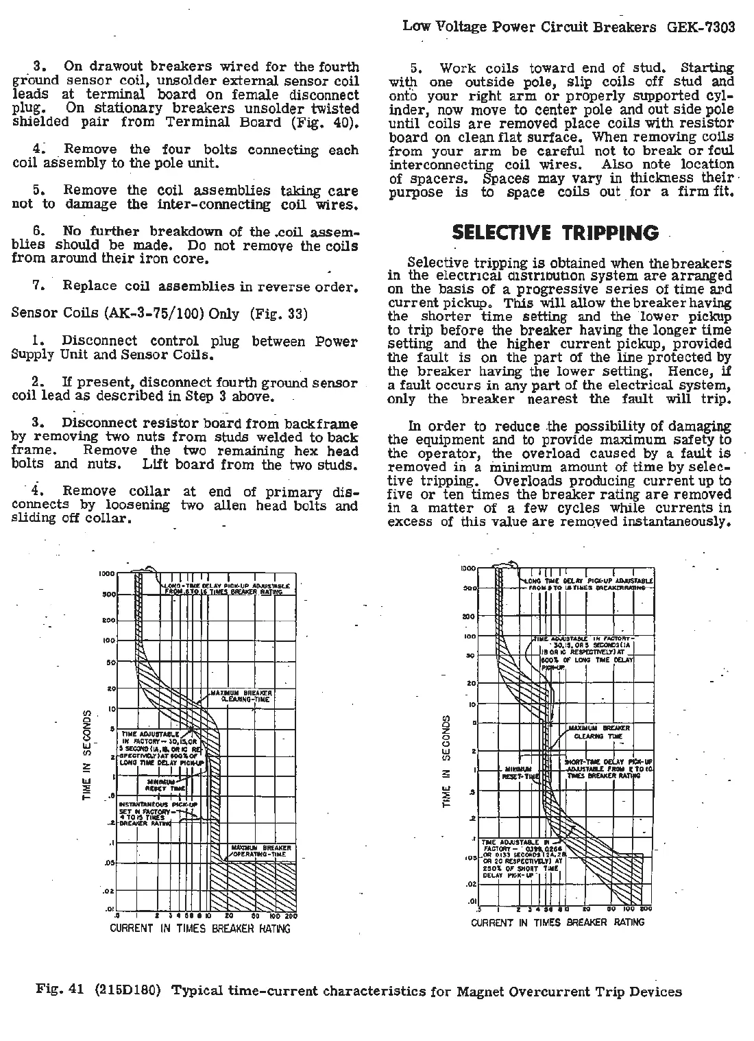
SELECTIVE
TRIPPING
.
Selective tripping
is
obtained when the
breakers
in
the
electrical
a1str1out1on
system
are
arranged
on the
basis
of a
progressive
series
of
time
avd
current
pickup.
This
will allow the
breaker
having
the
shorter
time
setting and the 1ow
er
pickup
to
trip
before the
breaker
having the lon
ger
time
setting and the higher
current
pickup, provided
the fault
is
on the ·
part
of the line
protected
by
the
breaker
having the lower setting. Hence, if
a fault
occurs
in any
part
of
the
electrical
system,
only the
breaker
nearest
the fault will
trip.
In
order
to reduce .the possibility of damaging
the
equipment and to provide maximum
safety
to
the operato
r,
the overload caused by a. fault
is
removed in a minimum amount of
time
by
se
le
c-
tive
tripping. Overloads producing
current
up
to
five
or
ten
times
the
breake
r
rating
are
removed
in
a
matter
of a
few
cycles while
currents
in
excess
of this
val
ue
are
rem
qved instantaneou
sly.
---
kJ
11111
I I I
HG
'TW[
OCI.
11
P<Cl<•UI'
ADJUST
ABU
FRO
M a
TO
1
.IT
ll<CS
8RCAl<l'.R1Up,.._
1000
soo
200
1,,1111£.
AO.N$TAIR.[ I N IM:fOrtr-
\ 1
·
so,o,.oAs
sa:ac>SUA
~
'
:g:~
~~~~
,--
" ,~
.......
I"
,-
~
100
90
zo
'\r--..:,
10
"
....
r,.,
"""""UM~
~
~TIM(
I/
I I -
--~
orl.Ar
_.,
,,__
..
,_
TA&.L
,_
'
TO
10
OESf:l'-T~
~
l'
~
~~
TNC AIWSTA81.C N -
~
,O
:~·r,;-"~~:-1~r:,
S
OR
2C:
llfSP£C:T1VII.T
>
AT
2SO\
OF
SHOAT
iifl
OCL~T
PIC:K•IP "I
~
I I
.0
.o
Tll€S IROl<ER
RATIIIG
-
~
-
"
-
~
~
---
'
~
~R
~~
~~
.,
I I ) 4
01
a
lO
tO
50
100
a11
CURRENT
IN
TIMES
BREAKER
RATING
Fig
. 41 (215Dl80) Typical
time-current
characteristics
for
Magnet Overcurrent
Trip
Devices

 Loading...


