EL
ECTR
IC
AL TRIPPING
-
The
breaker
may
be
tripped
electrically
by any
of tha
electrical
tripping devices
described
in
these
instructions.
. The
breaker
may also
be
tripped
by the automatic
overcurrent
or
reverse
current
tripping devices, if
so
equipped. All
these
devices
trip
the
breaker
inasimilarmanner,
i.e.
·the device
trip
arm
moves
against
the
trip
paddles
fastened on the
trip
shaft
, thus rotating
the
trip
shaft
and displacing the
trip
latch.
The
most
commonly
used
tripping device
is
the
shunt
trip
device connected in the control
circuit
as
shown
in
Fig.
1.
When a tripping
signal
is
given,
the shunt
trip
coil
is
energized through a nortrlally-
open auxiliary switch "
a"
-contact, thus tripping
· tbe
breaker.
. .
MAINTENANCE
BEFORE INSPECTION OR
ANY
MAINTENANCE
WORK
IS
DONE
BE
SURE THAT THE BREAKER
IS
IN THE OPEN POSITION. ALL ELECTRICAL
POWER, BOTH PRIMARY
AND
· CONTROL
SOURCES, SHOULD
ALSO
BE DISCONNECTED.
Warning: On
breakers
employing
stored-en-
ergy
closing mechanisms,
care
must
be
taken
when the
circuit
breaker
is
being
installed
and when any inspection
or
maintenance work
is
being done
so
that
the
breaker
is
in
the
open·
position
and the closing
springs
are
· being re15trained by
the
safety pin. The
proce-
dure
for
inserting
the safety pin
is
given below.
- INSERTING
SAFE
TY
PIN
-
AK
-5
0, -
75
and
-100
·
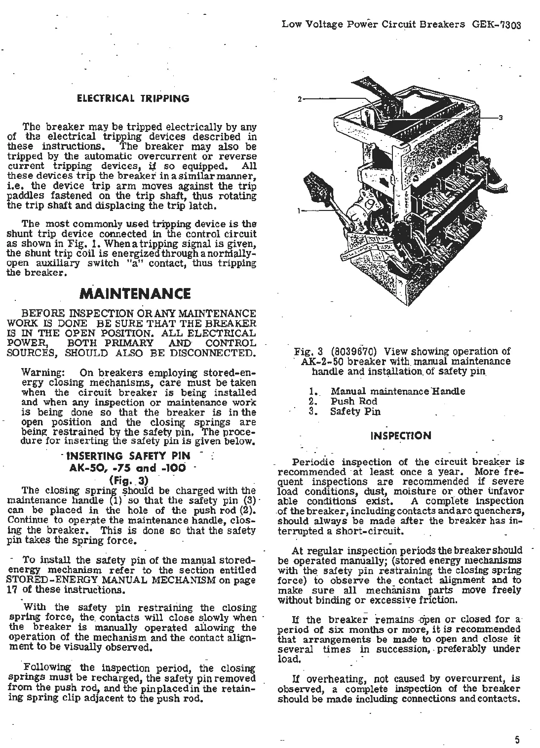
. (Fig
•.
3)
. .
The closing
sprini
~hould be charged with the
maintenance handle
(1)
so
that
the safety pin
(3)
-
can be
placed
in
the hole of the push
rod
(2).
Continue to op
er
.
ate
the maintenance· handle,
clos-
ing the
breaker.
This
is
done
so
that
the safety
pin
takes
the SJ?ring
force
.
- To il)stall the
safety
pin of the manµal
stored
-
energy mechanism
refer
to the
section
entitled
STORED- ENERGY MANUAL MECHANISM on page
17
of
these
instrucUons.
With the safety pin
restraining
the closing
spring
force, the. contacts will
close
s.lowly when ·
the
breaker
is
manually
operated
a1lowing the
operation
of the mechanism and the contact align-
ment
~o
be
visually observed.
. . -
.
!allowing
the inspection
period,
the closing
sprmgs
must be recharged, the
safety
pin
removed
from
the
push
rod, and the pin placed
in
the
retain-
ing
spring
clip adjacent to the push
rod.
Low Voltage
Power
Circ~it
Breakers
GEK-7303
Fig. 3 {8039670) View showing operation of
· AK-2-50 ·
breaker
with manual maintenance
handle and installation. of safety pin,
1.. Manual maintenance 'Handle
2.
Push
Rod
3.
Safety
Pin
INSPECTI
ON
Periodic
inspection of the
circuit
break~r
is
recommended ·
at
least
once a
year.
· More
fre-
quent inspections
are
recommended
if
severe
load. conditions, dust, moisture
or
_
other
unfavor
able conditions
exist.
A complete inspection
.of the
breaker,
including contacts and
arc
quenchers,
should always
be
made
after
the
breaker
has in-
terrupted
a
short-circuit.
At
regular
inspection periods the
breaker
should -
be
operated
manually; (stored energy mechanisms ·
with the
safety
pin
restraining the closing spring
force)
fo
observe
the contact alignment and to
make
sure
all
mechanism
parts
move freely
without binding
or
excessive friction.
If
the
breaker
remains
-open
or
closed
for
a·
period
of
six
months
or
more,
it
is
recommended
that
arrangements
.
be
made to open and close
it
several
times
in succession, . preferably under.
load.
If overheating, not caused by overcurrent,
is
observed, a complete inspection
of
the
breaker
should
be
made including connections and contacts.
5

 Loading...


