5.
Push
wire
through hollow tube of new
di$connect
assembly.
.
6~
Strip
in&ulation off end of
wire
to about
1/4
in.
from
the
end.
7.
Place
new contact tip on end of
wire
and
crimp.
8.
Pull
wire
through hollow tube
until
contact
tip
fits
snugly
against
· end of hollow tube.
9.
Crimp
tab
on
other
side
of
assembly
to
hold
wire
in
place.
10.
Any hollow
tubes
which
are
not
used
should
be
pushed
into
the
disconnect body and held
in
that
position
by
.
placing
fiber
spacer
s
over
inner
ends
of
tubes
and
spreading
tabs.
11.
When
all
wires
have
been
connected,
refasten
the
body
of
the
movable disconnect
assembly
to the
breaker
cross-channel.
· DRAWOUT
MECHANISM
.
(FIG •. 43)
Drawout
breakers
are
furnished with a drawout
mechanism
which
facilitates
the
inserting
and
withdrawing
of
the
breaker
from
its
enc
losure.
It
provides
a
suitable
menas
of
forcing
the
breaker
through
the
part
of
the
inserting
and withdrawal ·
operations
when
the
stationary
and movable halves
of
the
disconnects
. engage and_ disengage.
For
complete
details
of
inserting
and withdrawing
the
breaker,
such
as
the nuinber of racking handle
strokes
required
to
install
or
withdraw
the
breaker,
refer
to
instruction
ezEK-'Z302 furnished with the
breaker.
·
The
. ctr·awout
mechanism
is
·equipped with a
drawout
· t
rip
interlock
which
prevents
a racking
operation
from
being
performed
wlien the
breaker
is
closed.
Ins
erting
the
breaker
into
the
housing.
causes
the
racking
·
pins
.
on
the
housing
to
engage
the
semi
-
circular
slot
in
the
racking c~m (4).
In
this
position
the
breaker
is
ready
to
be
fully
racked-in
by
operating
the
racking handle (1).
The
·
first
upward
stroke
of the racking· handle
causes
the
racking
pin
on
the housing to engage
the
trip
interlock
link
and pin
assembly
(2, 3),
rotating
the
link
(2) and causing the pin (3) to
move
upward
against
the adjusting ~crew on the
interlock
trip
paddle.
This
trips
the
breaker
-and
. holds
it
trip-free
during
the
entire
racking_
opera
..
tion.
The
fifth
and
.
final
stroke
of
the
racking
handle
releases
the
·
trip
interlock
and allows
the
_
breaker
to
be
closed,
.
since
the
breaker
is
now\
fully
racked-in
. .
ADJUSTMEN'J'.S
(Fig.
43)
One
adjustment
on
the
trip
interlock
is
re:.
quired.
With
the
breaker
mechanism
in
the
re-
set
.
position
and
the
racking
cam
(4)
not engaging
the ·
racking
~ins
on
the
housing,
there
should
be
at
least
1/8in.
clearance
between the top edge
..
of
the
trip
interlock
pin
(3) and the adjusting
screw
on
the
interlock
trip
.
Low Voltage
Power
Circuit
Breakers
GEK-7303
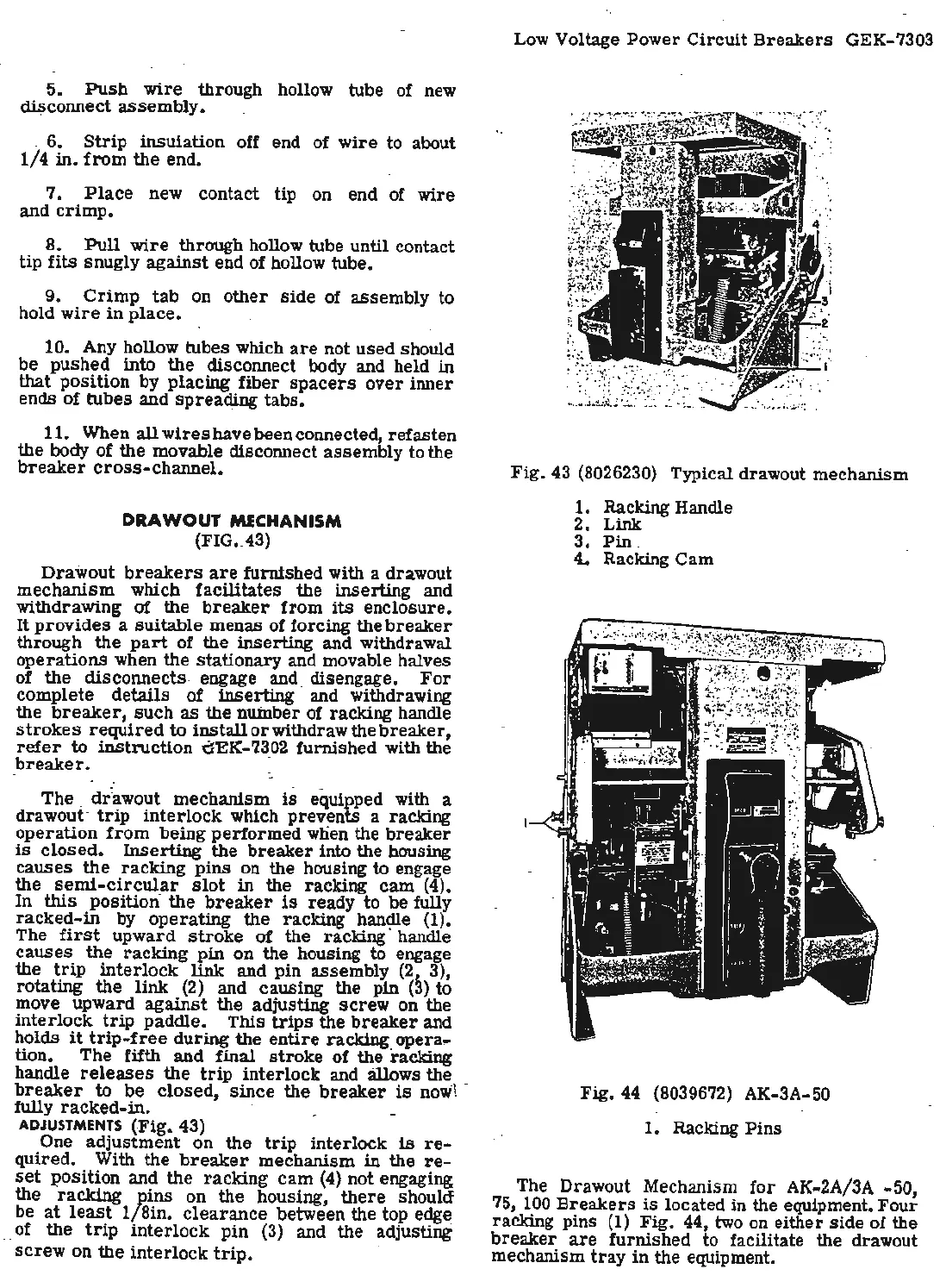
Fig
. 43 (8026230) Typical drawout me
chanism
1.
Racking Handle
2.
Link
. 3.
Pin
.
4..
Racking Cam
Fig.
44 (8039672) AK-3A-50
1.
Racking
Pins
The
Drawout Mechanism
for
AK-2A/3A -50,
75, 100
Breakers
is
located in the equipment.
Four
racking
pins
(1)
Fig.
44, two on
either
side
of
the
breaker
are
furnished
to facilitate the drawout
mechanism
tray
in
the equipment.

 Loading...


