GEK-7303
Low
Voltage Power
Circuit
Breakers
2
3
4
5.
I
.
I
--
---{;}
. .
6
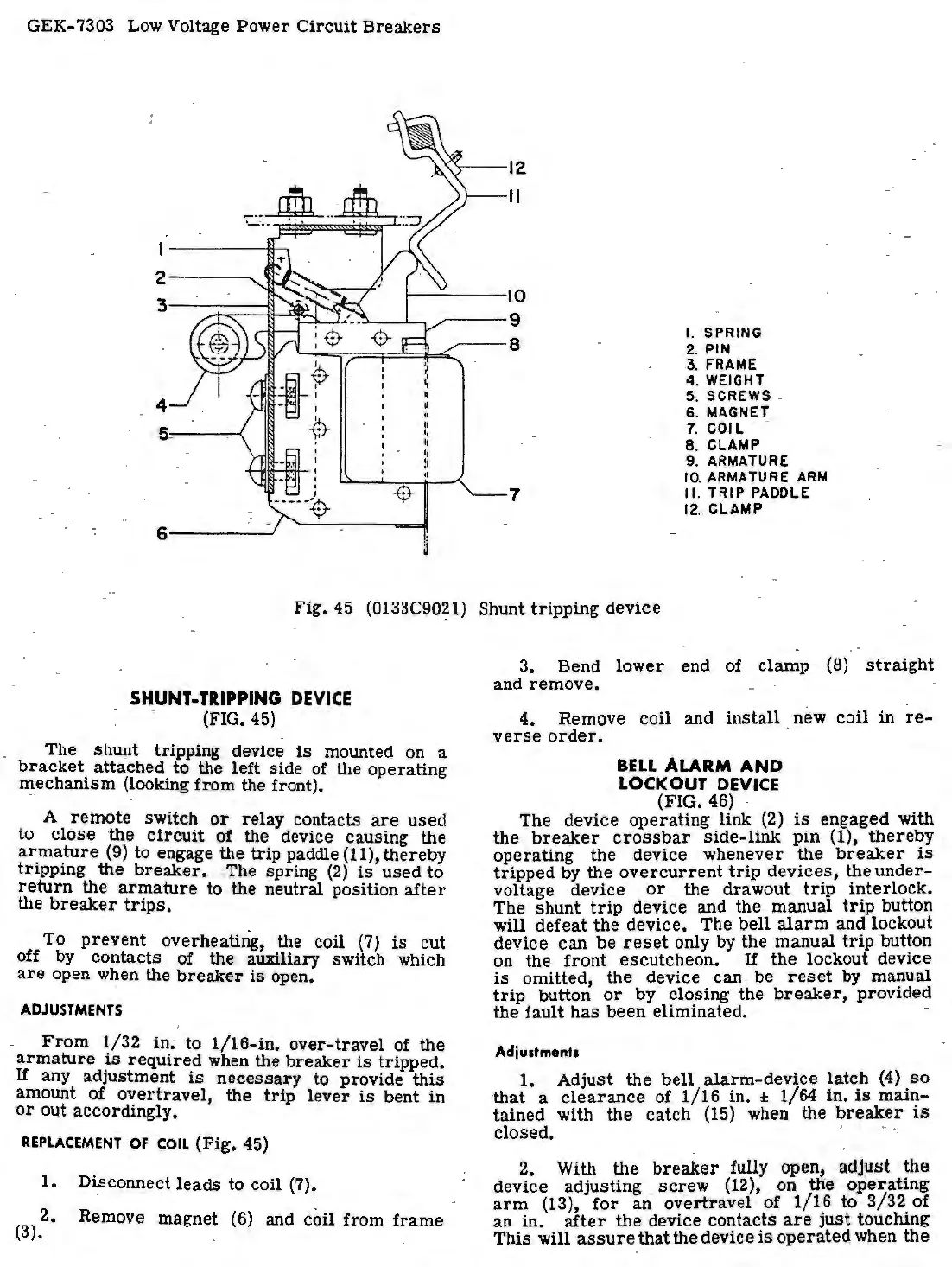
Fig.
45
SHUNT-TRIPPING
DEVICE
(FIG.
45)
•
II
•,
II
~
)
-$
a
(0133C90?
1)
The shunt tripping device
is
mounted on a
bracket
attached to the left side
of
the operating
m.echanism
(looking
from the front). ·
A
remote
switch
or
relay contacts
are
used
to close the
circuit
of the device causing the
ar_ma_ture
(9) to engage the trip paddle (11), thereby
tr1ppmg the
breaker.
The spring
(2)
is
used to
return
the
armature
to the neutral position
after
the
breaker
trips.
To
prevent
overheating, the coil
(7)
is
cut
off by contacts of the auxiliary switch which
are
open when the
breaker
is
open.
ADJUSTMENTS
From
1/32 in; to
1/16-in.
over-travel of the
armature
~s
required
when the
breaker
is
tripped.
If
any adJustment
is
necessary
to provide
this
amount of
overtravel,
the
trip
lever
is
bent
in
or
out accordingly.
REPLACEMENT
OF
COIL
(Fig. 45)
1. Di.sconnect
leads
to coil (7).
2. Remove magnet
(6)
and coil from
frame
(3).
10
9
I. SPRING
8
2.
PIN
3.
FRAME
4. WEIGHT
5. SCREWS .
6. MAGNET
7.
COIL
8. CLAMP
9. ARMATURE
10.
ARMATURE
ARM
1
.
II.
TRIP
PADDLE
12
..
CLAMP
Shunt tripping device
3.
Bend
lower
end of clamp
(8)
straight
and
remove.
4.
Remove coil anq
install
new
coil
in
re-
verse
order.
BELL
ALARM
AND
LOCKOUT DEVICE
(FIG.
46)
The device
operating
link (2)
is
· engaged with
the
breaker
crossbar
side-link
pin (1),
thereby
operating the device whenever
the
breaker
is
tripped
by the
overcurrent
trip
devices,
the
under-
voltage device
or
the drawout
trip
interlock.
The shunt
trip
device and the manual
trip
button
will defeat the device. The
bell
alarm
and lockout
device
can
be
reset
only by the manual
trip
button
on the
front
escutcheon. If the lockout device
is
omitted, the device can. be
reset
by manual
trip
button
or
by· closing the
breaker,
provided
the fault
has
been
eliminated.
Adjustments
1. Adjust the
bell
alarm-device
latch
(4)
so
that
a
clearance
of
1/16
in.
:t;
1/64 in.
is
main-
tained with the catch
(15)
when the
breaker
is
closed.
2. With the
breaker
fully open,
adjust
the
device adjusting
screw
(12), on the
operating
arm
(13),
for
an
overtravel of
1/16
to
3/32
of
an in.
after
the device contacts
are
just
touching
This will
assure
that the device
is
operated
when the

 Loading...


