GE MEDICAL SYSTEMS CT 9800 QUICK SYSTEM
Rev. 12 ➤ Indicates Change Direction 18000
4-12-16
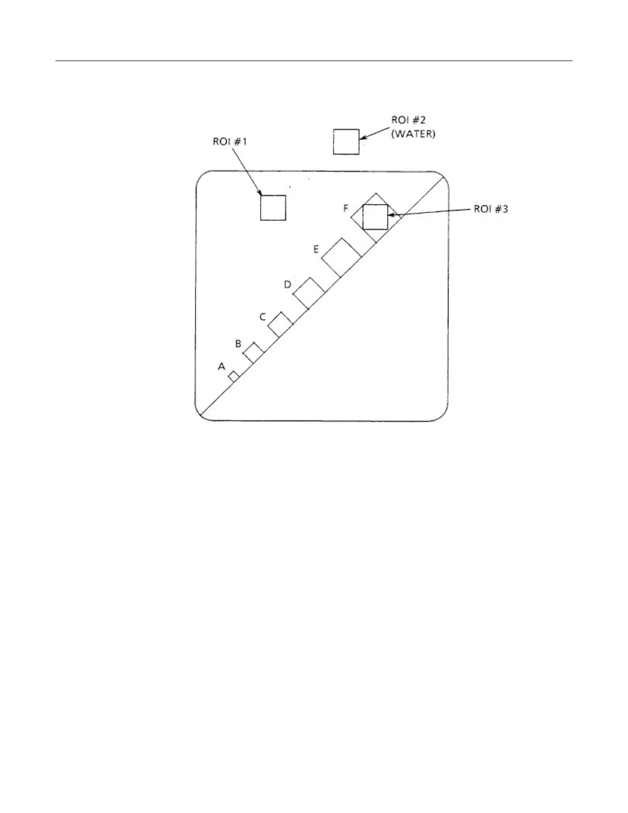
12-9-3 MTF Determination
LOCATION LINE PAIRS
PER CM.
RESOLUTION
(MM.)
A 10 0.5
B 8 0.6
C 6.25 0.8
D 5 1
E 3.9 1.3
F 3.1 1.6
ILLUSTRATION 4-12-5
RESOLUTION BAR PATTERNS
➤ The Modulation Transfer Function (MTF) is the ratio of the modulation of a test image produced by the system to
the modulation present in the original image. The MTF is a function of frequency and the test image, according to
MTF definition, should be a sine wave but, for practical purposes, bar patterns are often used instead. The QA
phantom has 6 bar patterns representing 6 frequencies. If a system has a MTF of 1 at a certain frequency, it
indicates a sine pattern of that frequency will be imaged perfectly. At the other extreme, a MTF of zero implies
the sine pattern will be completely blurred.
 Loading...


