GE MEDICAL SYSTEMS CT 9800 QUICK SYSTEM
Rev. 12 Direction 18000
6-9A-4
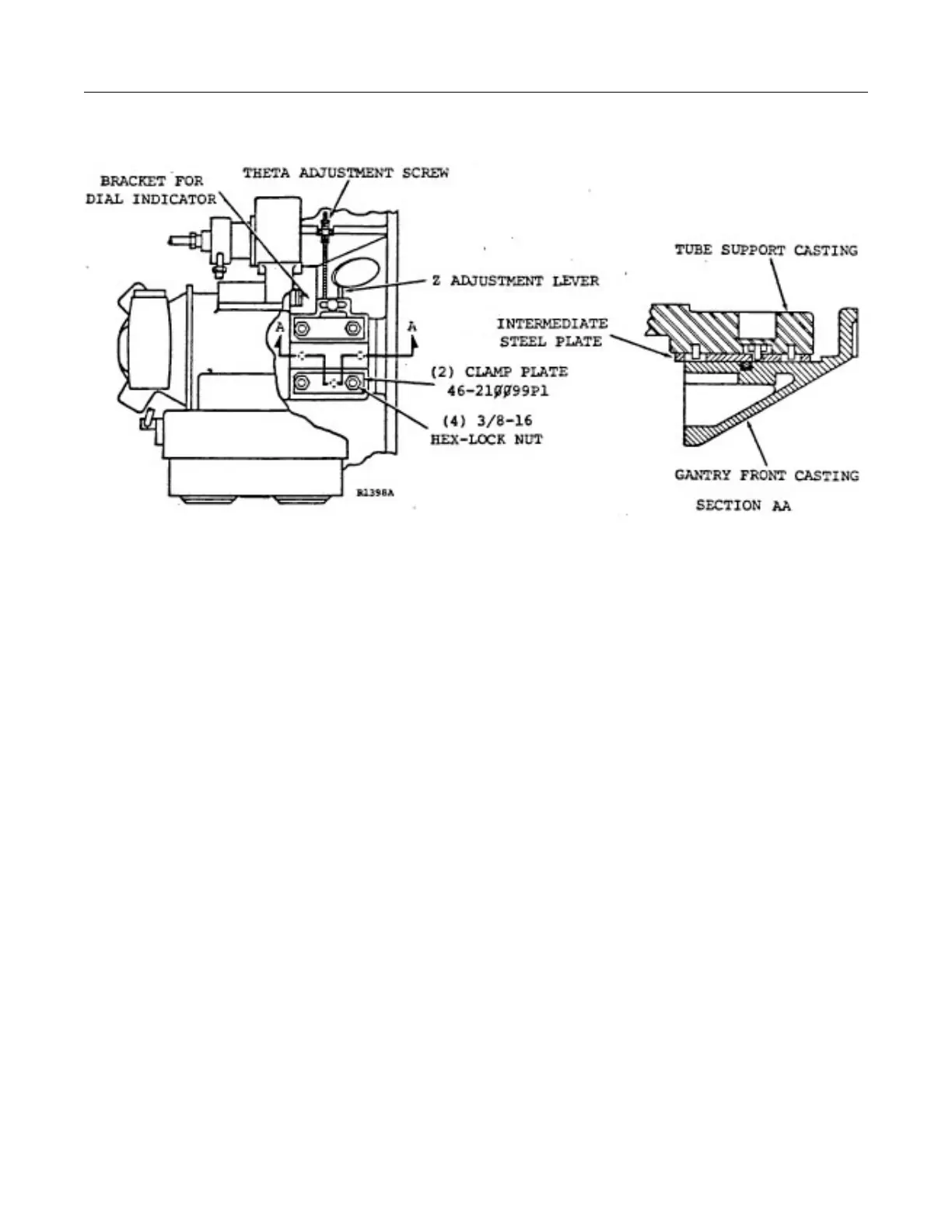
ILLUSTRATION 6-9A-3
Adjustment of tube position is done with the gantry at a theta position of -90° or +270° (tube at 3:00 O’clock
position). In this position, the tube is accessible through the right side of the gantry without opening the front
gantry cover.
WARNING: NEVER ATTEMPT TO ADJUST THE TUBE POSITION WITHOUT TURNING THE GANTRY
SCAN DRIVE SWITCH OFF.
Both Z and theta adjustments require that the four (4) 3/8-16 lock nuts be loosened. The Z adjustment must be
done first as it is less critical than theta. Both should be done using a dial indicator to measure that amount of
change in tube position. Always zero the indicator before loosening the mounting hardware, then note the amount
of indicator shift as the clamp nuts are loosened so as to compensate for shift on re-tightening.
To move the tube in the Z direction, loosen the knurled lock nut on the Z lever and move the lever in the same
direction as the desired Z shift. After repositioning the tube, tighten the knurled knob of the Z shift lever before
tightening the two clamp plates.
Tube shift in the theta direction is done using the differential threaded adjustment above the clamp plates. Details
of the mechanism are shown in Illustration 6-9A-4. Also shown in the illustration is the method of attaching a dial
indicator to the bracket so that the amount of tube shift can be monitored. The dial indicator is secured to the
bracket with a special nut and bolt shown in Illustration 6-9A-4, and adjusted for a 0 reading before the tube
clamps are loosened. After loosening the clamps, raise or lower the tube using the differential screw adjustment.
One clockwise turn of the adjustment raises the tube 0.021” (0.53mm). Snug the clamp plates before checking
actual tube shift on the dial indicator. After the required tube shift is obtained, tighten the four clamp plate lock
nuts and torque to 30 ± 3.0 ft.lbs.
 Loading...


