GE MEDICAL SYSTEMS CT 9800 QUICK SYSTEM
Rev. 16 Direction 18000
6-9A-7
3. Detector
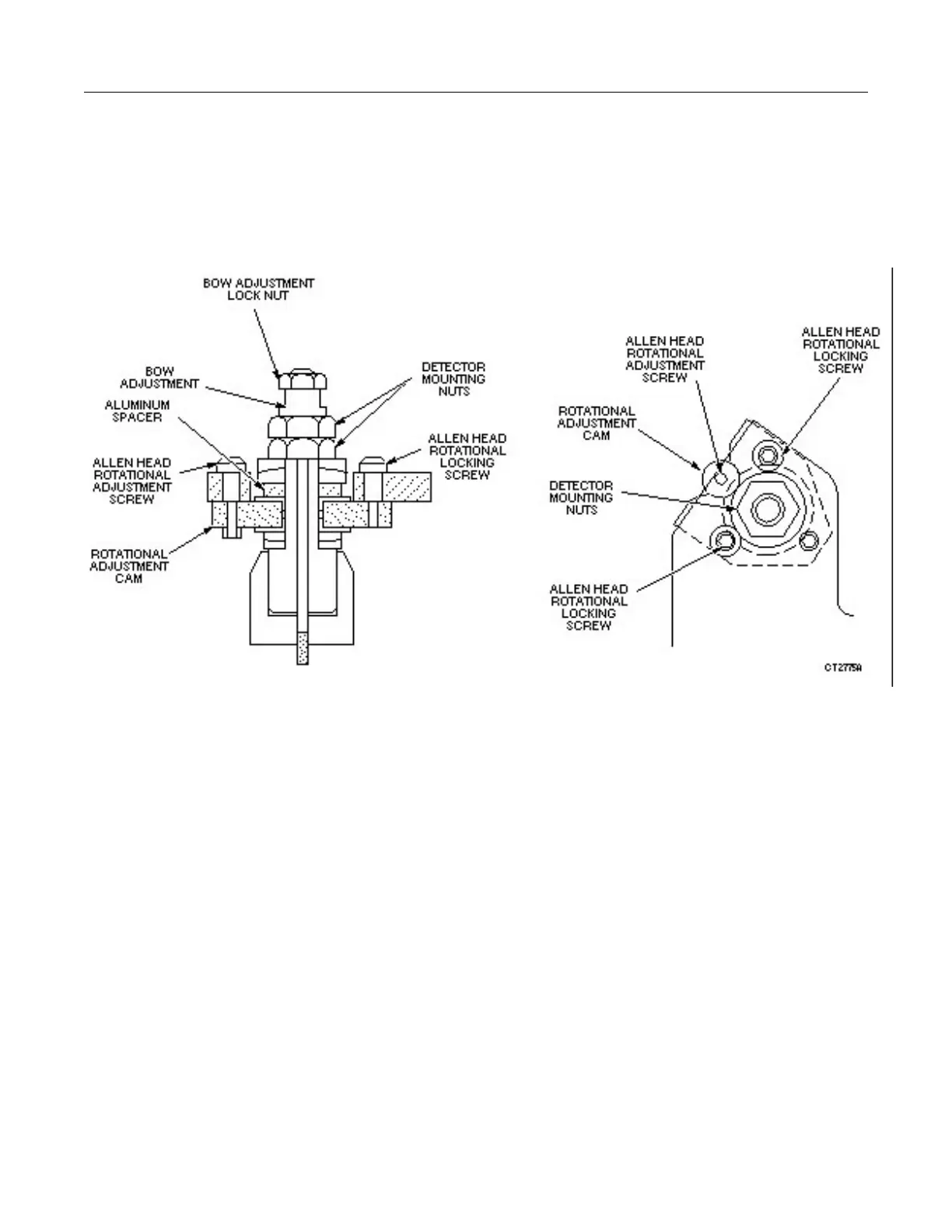
Refer to Illustration 6-9A-7. The detector is supported to the gantry mounting plate with three mounts. Each
mount has an adjustable positioning screw to move the detector in the Z direction. In addition, the HiLight
detector’s radial alignment is adjustable through the use of a cam on the high channel end of the detector. The
detector is not adjustable in the theta direction.
ILLUSTRATION 6-9A-7
DETAIL OF MOUNTING/ADJUSTMENT HARDWARE
To adjust the radial position (only at detector installation):
Loosen the large detector mounting nuts so that they are finger-tight. See figure 6-9A-7.
Loosen the allen head rotational adjustment locking screws.
Move the detector using the cam.
Tighten the allen head rotational adjustment locking screws.
Torque the inside detector mounting nuts to 25 ft-lbs. When the inside nuts have been torqued, torque the
outside nuts to 25 ft-lbs while holding the inside nut from turning. If a torque wrench is not available the nuts
should be tightened finger tight and then tightened 1/2 flat with a wrench.
To adjust the Z-axis position (BOW):
Loosen all three sets of the detector lock nuts and mounting nuts, even if only one or two mounts need
adjustment.
Loosen only the adjustment locking nuts (7/16”) on the mounts which require adjustment.
Turn the adjustment stud by the number of flats specified in the BW program. One flat = 1/6th of a turn.
 Loading...


