GE MEDICAL SYSTEMS CT 9800 QUICK SYSTEM
Rev. 6 Direction 18000
6-10-9
10-5 - Alignment of Internal Axial Laser Lights, Left and Right
ILLUSTRATION 6-10-5
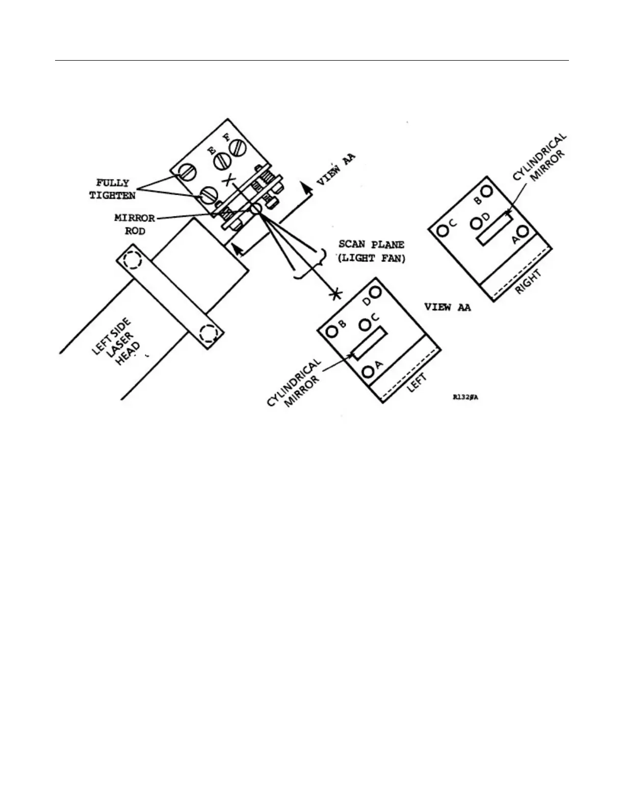
INTERNAL AXIAL LASER LIGHT
CAUTION: The alignment light adjustment screws must be handled carefully, i.e., do not
overtorque the screws. Failure to heed this caution, may cause damage to the
alignment light adjustments.
The maximum allowed scan axis to beam misalignment is ± 1.5mm
In general, the screw adjustments for setting up the left and right internal lights are as follows. Refer to Ill. 6-10-5:
---Screws “A”, “B” and “C” can be turned the same amount in the same direction to move the cylindrical
mirror into and out of the beam.
---Screw “A” moves the beam vertically across the gantry opening.
---Screws “B” and “C” moves the beam in and out of the scan plane.
---Screw “D” locks the final adjustments in place.
---Screws “E” and “F” are used to remove skew from the beam (i.e., situation where the beam fan is
angulated to the scan plane).