GE Grid Solutions
994-0081-3.00-21 GE Information
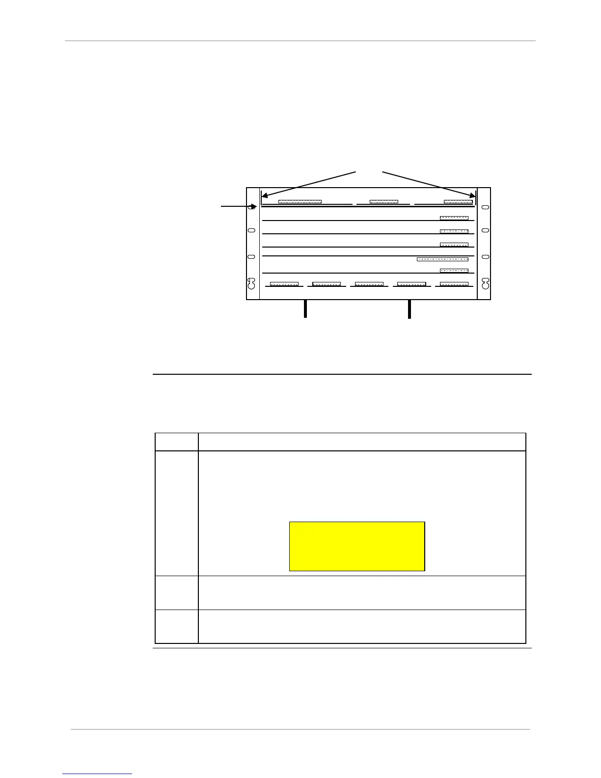
Shelf Plate, Continued
Shelf Plate
Location
Each of the three cards on the Shelf Plate is connected to the WESDAC
Board through a DIN connector.
Locking Brackets
Shelf Plate
Field terminations for the Power Supply are made through a five-pin
connector positioned on the back panel of the D25.
Procedure:
Removing the
Shelf Plate
How to remove the shelf plate.
After removing all connections from the IED/RTC and XCOM cards:
Step Action
1 Locate the two levers that secure the metal Shelf Plate in the D25
housing.
Two labels, one on each side panel inside the enclosure, identify
the Locking Bracket locations.
2 Lift the front end of the locking bracket levers until they click into
the up position.
3 Carefully slide the Shelf Plate and attached cards out of the
housing.
TO