GE Grid Solutions
994-0081-3.00-21 GE Information
CT/PT Modules, Continued
Procedure:
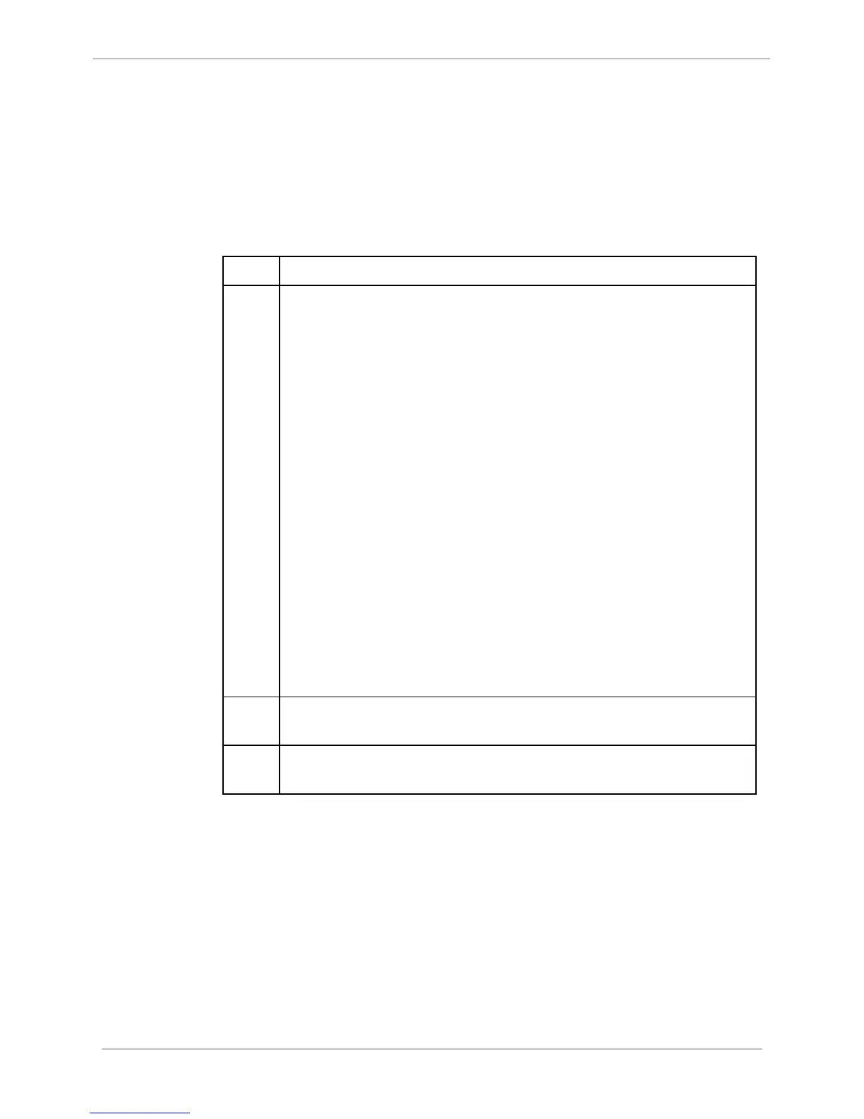
Over-current
Range
Calibration
(195% - F.S.)
Steps to calibrate the transformer for inputs in the over-current range.
Step Action
1.
Using SGConfig:
• Set the calibration and correction factors for the phase and magnitude
to the following default values:
1.00000 for magnitude, and 0.00000 for phase.
− To set the calibration factors, go to
D25 AC Configuration>Calibration tab>Internal Calibration tab
− To set the correction factors, go to
D25 AC Configuration >Calibration tab>External Correction tab.
• Set the configured frequency to match the test signal’s frequency
(either 50 or 60 Hz).
− To set the configured frequency, go to:
D25 DCA Configuration>Advanced tab>Line Frequency
• Set each input’s magnitude point Report Deadband to zero and
Averaging ON.
− To set the Report Deadband, go to:
D25 AC Configuration>I/O Configuration tab>Physical AC
Analog Inputs>Report Deadband
− To set the Averaging, go to:
D25 AC Configuration>I/O Configuration tab>Physical AC
Analog Inputs>Averaging
2.
Generate and download the configuration to the unit you are
calibrating.
3.
For each input use a precision AC current source to inject the test
currents indicated in the table in Step 4