GE Grid Solutions
GE Information 994-0081-3.00-21
CT/PT Modules, Continued
Procedure: Over-current Range Calibration (195% - F.S.) (continued)
Step Action
4.
Using the D25 AC Input Engineering Value Displays (available
through the B050-0 WESMAINT application), record the raw
magnitude values for each input you are calibrating.
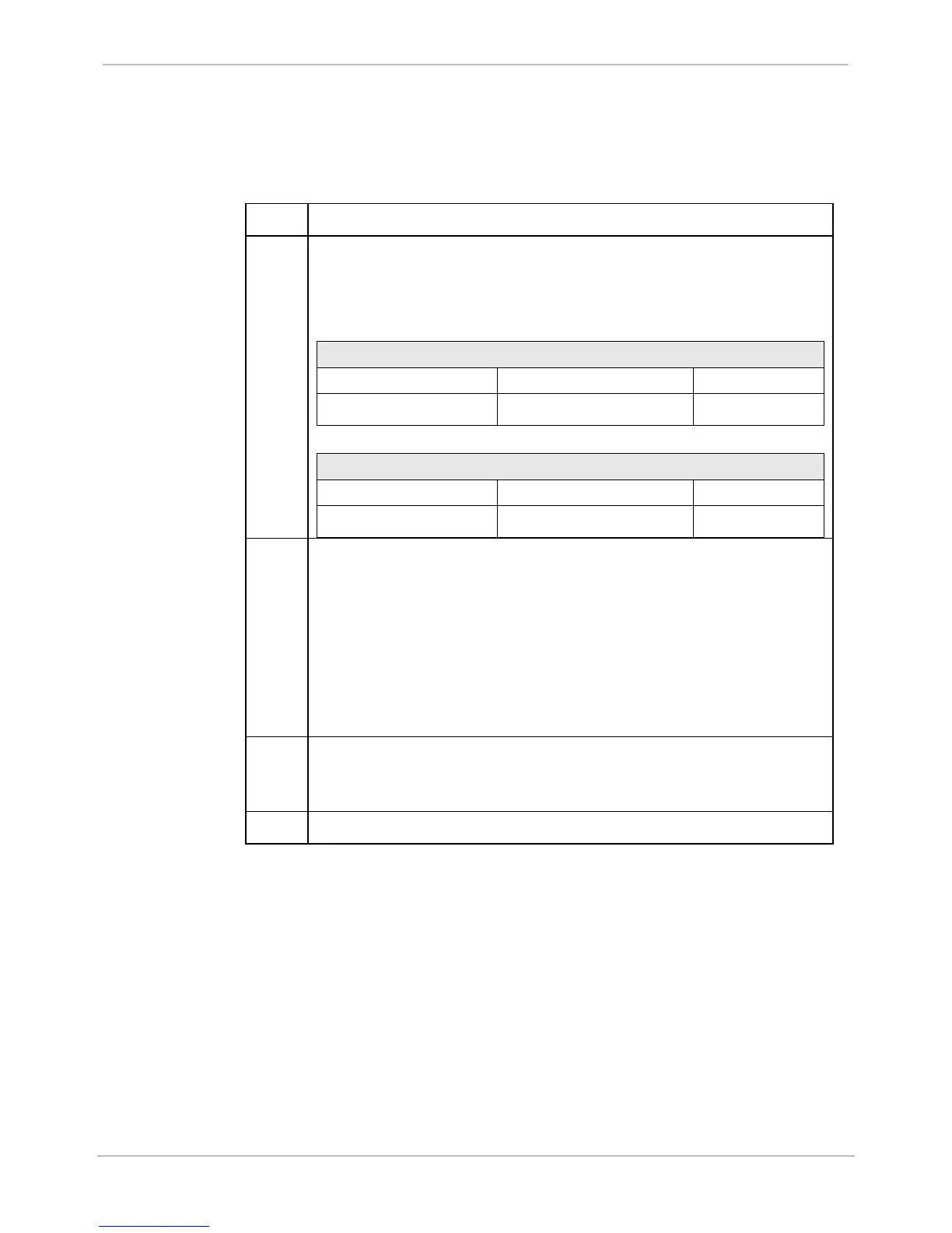
Verify that the reported values are within the following tolerances:
CT Type: 1A Part Number: 450-0107
For Test Current… Expected Raw Value is… Tolerance
4.000 A
rms
± 0.05% 8192 ± 200 counts
CT Type: 5A Part Number: 450-0108
For Test Current… Expected Raw Value is… Tolerance
20.000 A
rms
± 0.05% 8192 ± 200 counts
5.
Calculate the 195-FS magnitude calibration factor for each input
using the data gathered in Step 4.
Use the following formula:
Magnitude Calibration Factor = expected value / measured value
For example, if the measured value is 8195, the magnitude
calibration factor is:
8192/8195 = 0.99963
6.
Enter the calibration factors in the Magnitude (195% - FS) for each
input into the configuration (under D25 AC Configuration >
Calibration tab > Internal Calibration tab).
7.
Generate and download the configuration to the unit.