GE Grid Solutions
GE Information 994-0081-3.00-21
Control Outputs, Continued
D25KE FACE-
40 Combined
R/L and T/C
Trip/Close and Raise/Lower digital outputs can be used on the same D25KE
FACE-40 unit.
When assigning raise/lower groups, always start with group 4, then group 3,
and lastly group 2.
Remember that raise/lower points number in the reverse direction from other
point types: point 32 will become lower point 1.
Note
Configuring raise/lower groups with numbers lower than the trip/close group
numbers, or between trip/close groups can result in a very complex and
confusing wiring scheme.
G1 and G2
Connections
for: 3 Groups
of Trip/Close,
and One Group
of Raise/Lower
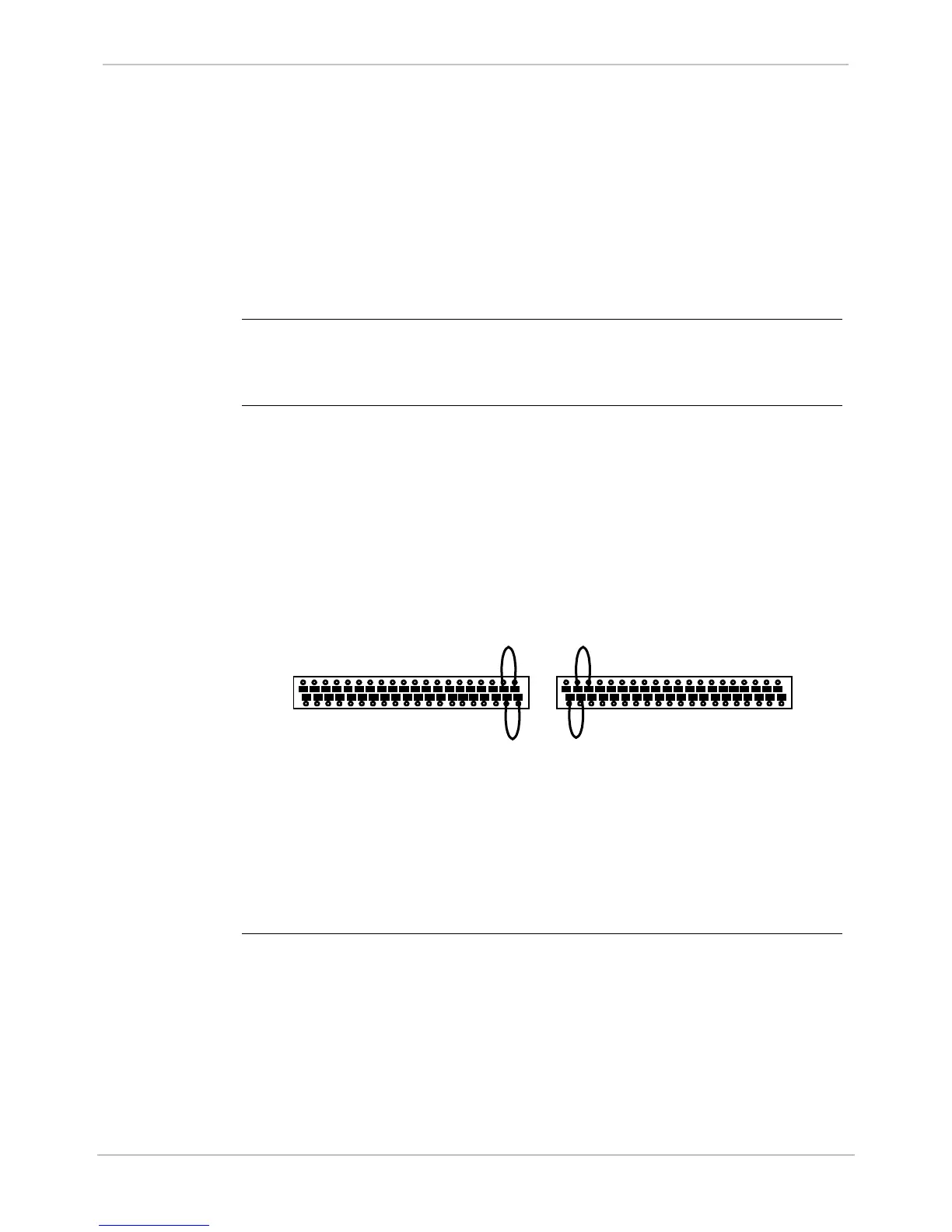
Jumpering is required to configure a D25KE FACE-40 module for 3 groups
of trip/close, and one group of raise/lower:
Use jumper wires on the FACE-40 terminal block G1 to configure groups 1
and 2.
• Group 1:
− connect between MTA (G1-39) and JMP1 (G1-37)
• Group 2:
− connect between MTA (G1-40) and JMP2 (G1-38)
1 3 5 7 9 11 13 15 17 19 21 23 25 27 29 31 33 35 37 39
2 4 6 8 10 12 14 16 18 20 22 24 26 28 30 32 34 36 38 40
G1
1 3 5 7 9 11 13 15 17 19 21 23 25 27 29 31 33 35 37 39
2 4 6 8 10 12 14 16 18 20 22 24 26 28 30 32 34 36 38 40
G2
Use jumper wires on the FACE-40 terminal block G2 to configure groups 3
and 4.
• Group 3 for trip/close:
− connect between MTB (G2-5) and JMP3 (G2-3)
• Group 4 for raise/lower:
− connect between VCB (G2-2) and JMP4 (G2-4)