GE Grid Solutions
994-0081-3.00-21 GE Information
Control Outputs, Continued
D25KE FACE-
40
Raise/Lower
Configuration
The 32 digital outputs can be configured as four groups of four Raise/Lower
pairs.
Note: The control voltage can be up to 120 Vdc. See page 152 for
specifications of control outputs.
G1 and G2
Connections for
Raise/Lower
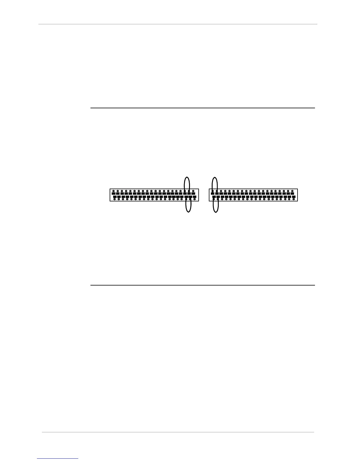
Use jumper wires on the FACE-40 terminal block G1 to configure groups 1
and 2.
• Group 1:
− connect between VCA (G1-35) and JMP1 (G1-37)
• Group 2:
− connect between VCA (G1-36) and JMP2 (G1-38)
1 3 5 7 9 11 13 15 17 19 21 23 25 27 29 31 33 35 37 39
2 4 6 8 10 12 14 16 18 20 22 24 26 28 30 32 34 36 38 40
G1
1 3 5 7 9 11 13 15 17 19 21 23 25 27 29 31 33 35 37 39
2 4 6 8 10 12 14 16 18 20 22 24 26 28 30 32 34 36 38 40
G2
Use jumper wires on the FACE-40 terminal block G2 to configure groups 3
and 4.
• Group 3:
− connect between VCB (G2-1) and JMP3 (G2-3)
• Group 4:
− connect between VCB (G2-2) and JMP4 (G2-4)