Home
GE
Relays
D30
Page 371
GE D30 - Page 371
686 pages
Manual
Save Page as PDF
To Next Page
To Next Page
To Previous Page
To Previous Page
Loading...
CHAPTER 5: SETTINGS
SYSTEM SETUP
D30 LINE DIST
ANCE PROTECTION SYSTEM – INSTRUCTION MANUAL
5-161
5
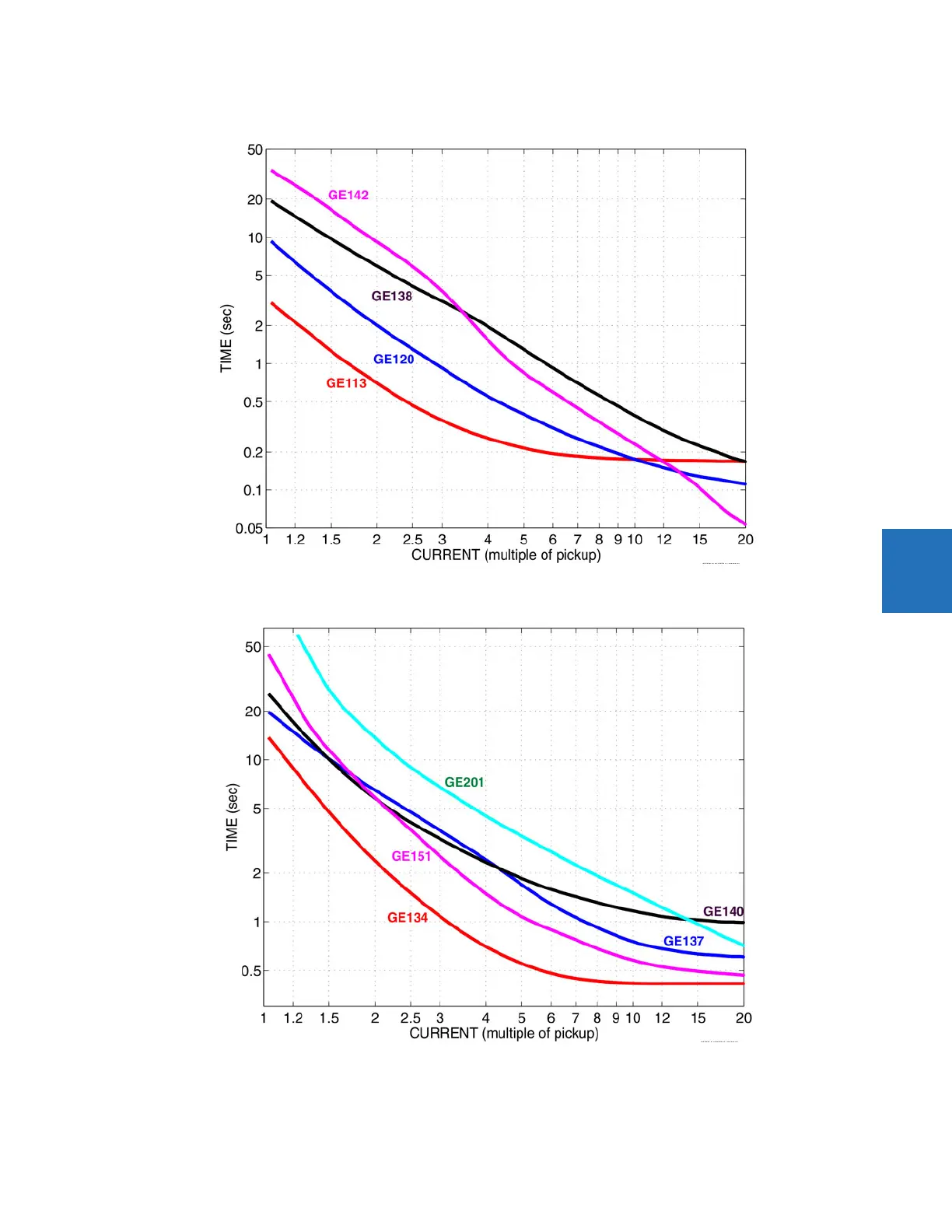
Figure 5-78: R
ecloser curves GE113, GE120, GE138, and GE142
Figure 5-79: Recl
oser cur
ves GE
134, GE137, GE140, GE151, and GE201
370
372
Table of Contents
Main Page
Default Chapter
3
Table of Contents
3
1 Introduction
11
Safety Symbols and Definitions
11
General Cautions and Warnings
11
For Further Assistance
12
2 Product Description
15
Security
17
Order Codes
21
Order Codes with Enhanced CT/VT Modules
22
Order Codes with Process Bus Modules
25
Replacement Modules
27
Signal Processing
30
UR Signal Processing
30
Specifications
32
Protection Elements
32
User-Programmable Elements
39
Monitoring
41
Metering
41
Inputs
42
Power Supply
44
Outputs
44
Communication Protocols
46
Inter-Relay Communications
47
Cybersentry Security
49
Graphical Front Panel
49
Environmental
49
Type Tests
50
Production Tests
51
Approvals
51
Maintenance
51
3 Installation
53
Unpack and Inspect
53
Panel Cutouts
54
Horizontal Units
54
Vertical Units
58
Rear Terminal Layout
63
Wiring
66
Typical Wiring
66
Dielectric Strength
67
Control Power
67
CT/VT Modules
68
Process Bus Modules
70
Contact Inputs and Outputs
70
Transducer Inputs and Outputs
82
RS232 Port
84
CPU Communication Ports
85
Irig-B
87
Direct Input and Output Communications
88
Description
88
Fiber: LED and ELED Transmitters
90
Fiber Laser Transmitters
90
Interface
91
RS422 Interface
95
RS422 and Fiber Interface
97
And Fiber Interface
98
IEEE C37.94 Interface
98
C37.94SM Interface
101
Activate Relay
104
Install Software
105
Enervista Communication Overview
105
System Requirements
106
Install Software
107
Add Device to Software
108
Set IP Address in UR
109
Configure Serial Connection
114
Configure Ethernet Connection
116
Configure Modem Connection
117
Automatic Discovery of UR Devices
117
Connect to the D30
118
Connect to the D30 in Enervista
118
Use Quick Connect Via Front RS232 Port
119
Use Quick Connect Via Front USB Port
120
Use Quick Connect Via a Rear Ethernet Port
120
Set up Cybersentry and Change Default Password
121
Import Settings
122
Connect to D400 Gateway
123
Oscillography Files
123
Event Records
123
Log Files
123
Setting Files
124
4 Interfaces
125
Enervista Software Interface
125
Introduction
125
Settings Files
125
Event Viewing
126
File Support
127
Enervista Main Window
127
Protection Summary Window
128
Settings Templates
129
Secure and Lock Flexlogic Equations
133
Settings File Traceability
136
Front Panel Interface
139
Front Panel
139
Front Panel Display
141
Front Panel Navigation Keys
161
LED Indicators
162
Front Panel Labelling
167
Menu Navigation
174
Change Settings
176
View Actual Values
181
Breaker Control
182
Change Passwords
183
Invalid Password Entry
184
Logic Diagrams
185
Flexlogic Design Using Engineer
186
Design Logic
188
Send File to and from Device
198
Monitor Logic
199
View Front Panel and Print Labels
200
Generate Connectivity Report
201
Preferences
201
Toolbars
205
5 Settings
211
Settings Menu
211
Overview
214
Introduction to Elements
214
Introduction to AC Sources
215
Product Setup
217
Security
217
Display Properties
235
Graphical Front Panel
237
Clear Relay Records
249
Communications
250
Modbus User Map
317
Real Time Clock
317
Fault Reports
322
Oscillography
324
Data Logger
326
User-Programmable Leds
327
User-Programmable Self Tests
332
Control Pushbuttons
332
User-Programmable Pushbuttons
334
Flex State Parameters
340
User-Definable Displays
341
Direct Inputs/Outputs
343
Teleprotection
349
Remote Resources
350
Remote Resources Configuration
350
AC Inputs
352
System Setup
352
Power System
353
Signal Sources
354
Breakers
356
Disconnect Switch Control
362
Flexcurves
367
Flexlogic
374
Flexlogic Operands
374
Flexlogic Rules
387
Flexlogic Evaluation
387
Flexlogic Equation Editor
392
Flexlogic Timers
392
Flexelements
392
Non-Volatile Latches
397
Grouped Elements
398
Overview
398
Setting Group 1
398
Line Pickup
398
Distance
401
Power Swing Detect (ANSI 68)
419
Load Encroachment
428
Phase Current
429
Neutral Current
441
Wattmetric Ground Fault
449
Ground Current
453
Negative Sequence Current
456
Voltage Elements
462
Control Elements
469
Overview
469
Trip Bus
469
Setting Groups
471
Selector Switch
472
Underfrequency (ANSI 81U)
479
Frequency Rate of Change (ANSI 81R)
480
Synchrocheck (ANSI 25)
482
Autoreclose (ANSI 79)
487
Digital Elements
493
Digital Counters
496
Monitoring Elements
498
Inputs/Outputs
512
Contact Inputs
512
Virtual Inputs
514
Contact Outputs
515
Virtual Outputs
518
Resetting
518
Direct Inputs and Outputs
519
Teleprotection
523
Transducer Inputs/Outputs
525
Dcma Inputs
525
RTD Inputs
526
Dcma Outputs
527
Testing
531
Test Mode Function
531
Test Mode Forcing
531
Force Contact Inputs
532
Force Contact Outputs
532
6 Actual Values
535
Actual Values Menu
535
Front Panel
537
Enhanced and Standard Front Panels
537
Graphical Front Panel
538
Status
538
Contact Inputs
538
Virtual Inputs
538
Rxgoose Boolean Inputs
539
Rxgoose DPS Inputs
539
Teleprotection Inputs
539
Contact Outputs
539
Virtual Outputs
540
Autoreclose
540
Rxgoose Status
540
Rxgoose Statistics
541
Digital Counters
541
Selector Switches
541
Flex States
542
Ethernet
542
Real Time Clock Synchronizing
542
Direct Inputs
543
Direct Devices Status
543
Teleprotection Channel Tests
544
Incipient Fault Detector
544
Remaining Connection Status
544
Parallel Redundancy Protocol (PRP)
545
Txgoose Status
545
Metering
546
Metering Conventions
546
Sources
550
Synchrocheck
553
Tracking Frequency
554
Frequency Rate of Change
554
Flexelements
554
Rxgoose Analogs
555
Wattmetric Ground Fault
555
Transducer Inputs/Outputs
555
Distance
556
Records
557
Fault Reports
557
Event Records
558
Oscillography
560
Data Logger
560
Product Information
561
Breaker Maintenance
561
Model Information
561
Firmware Revisions
562
7 Commands and Targets
565
Commands Menu
565
Virtual Inputs
566
Clear Records
566
Set Date and Time
567
Relay Maintenance
567
Security
568
Targets Menu
569
Target Messages
569
Relay Self-Tests
570
8 Application of Settings
579
Application Guidelines
579
Overview
579
Impact of Memory Polarization
579
High Set Overcurrent Elements
579
Distance Elements (Stepped Distance Scheme)
580
Phase Distance
580
Ground Distance
581
Series Compensated Lines
583
Overview
583
Distance
584
Ground Directional Overcurrent
585
High-Set Phase Overcurrent
585
Phase Distance through Power Transformers
586
Phase Distance Protection
586
Example
587
9 Theory of Operation
589
Distance Elements
589
Overview
589
Phasor Estimation
590
Distance Characteristics
590
Fast Distance Algorithm
595
Memory Polarization
595
Distance Elements Analysis
597
Phase Distance Applied to Power Transformers
599
Description
599
Example
603
Ground Directional Overcurrent
605
Description
606
Fault Locator
610
10 Maintenance
615
Devices with Site Targets
615
Data with Modbus Analyzer
615
Monitoring
615
General Maintenance
617
In-Service Maintenance
617
Out-Of-Service Maintenance
617
Retrieve Files
617
Unscheduled Maintenance (System Interruption)
617
Convert Device Settings
619
Compare Settings
621
Compare against Defaults
621
Back up and Restore Settings
622
Copy Settings to Other Device
621
Back up Settings
622
Restore Settings
625
Upgrade Software
627
Upgrade Firmware
628
Replace Front Panel
629
Replace Module
637
Battery
638
Replace Battery for SH/SL Power Supply
638
Dispose of Battery
640
Clear Files and Data after Uninstall
643
Repairs
643
Disposal
644
Storage
644
A.1 Flexanalog Items
645
Flexanalog Items
645
B Radius Server
655
RADIUS Server Configuration
655
C Command Line
657
Command Line Interface
657
D.1 Warranty
663
Warranty
663
Revision History
663
Related product manuals
GE D30D00HCHF8AH6AM6BP8BX7A
646 pages
GE DGP Series
278 pages
GE D30 series
636 pages
GE B90
510 pages
GE C60
682 pages
GE 345
82 pages
GE 369
136 pages
GE 489
306 pages
GE T60
770 pages
GE 269Plus
218 pages
GE UR series
652 pages
GE Multilin 489
314 pages