5-106 G30 Generator Protection System GE Multilin
5.4 SYSTEM SETUP 5 SETTINGS
5
b) GENERAL TRANSFORMER SETTINGS
PATH: SETTINGS SYSTEM SETUP TRANSFORMER GENERAL
The general transformer settings apply to all windings. Settings specific to each winding are shown in the following section.
• PHASE COMPENSATION: Selects the type of phase compensation to be performed by the relay. If set to “Internal
(software)”, the transformer phase shift is compensated internally by the relay algorithm. If set to “External (with CTs)”,
the transformer phase shift is externally compensated by the CT connections.
c) WINDINGS 1 TO 2
PATH: SETTINGS SYSTEM SETUP TRANSFORMER WINDING 1(2)
The settings specific to each winding are shown above.
The following discussion is applicable to the G30 device protecting the GSU, assuming that the LV winding CTs are on the
neutral side of the generator and the HV winding CTs are on the system side of the step-up delta-wye transformer. It is also
assumed that CTs are differentially connected as per regular transformer differential applications, as shown in the Typical
wiring, VT on the LV side of the Transformer diagram in the Applications of Settings chapter.
The flexibility of G30 phase compensation allows the wiring of CTs to have polarities looking inside the protected zone or
looking into the system. This may be needed to provide correct forward metered power at both sides of the GSU. When
CTs are differentially connected (wired with polarities both pointing inside the zone), the angle between winding currents
should be 0° plus an additional phase shift caused by the wye-delta connection of the transformer. When CTs are wired to
point into the system, the angle between winding currents should be 180° plus an additional phase shift caused by the wye-
delta connection of the transformer. Therefore, the adopted CTs polarities must be taken into account in the
SYSTEM SETUP
TRANSFORMER settings menu. Refer to the Applications of Settings chapter for examples of setting up G30 transformer
differential protection with different CT polarity options.
Transformer differential protection uses the following calculated quantities (per phase): fundamental, second harmonic, and
fifth harmonic differential current phasors, and restraint current phasors. This information is extracted from the current
transformers (CTs) connected to the relay by correcting the magnitude and phase relationships of the currents for each
winding, so as to obtain zero (or near zero) differential currents under normal operating conditions. Traditionally, these cor-
rections were accomplished by interposing CTs and tapped relay windings with some combination of CT connections.
The G30 simplifies these configuration issues. All CTs at the transformer are connected wye (polarity markings pointing
away from the transformer). User-entered settings in the relay characterizing the transformer being protected and allow the
relay to automatically perform all necessary magnitude, phase angle, and zero-sequence compensation.
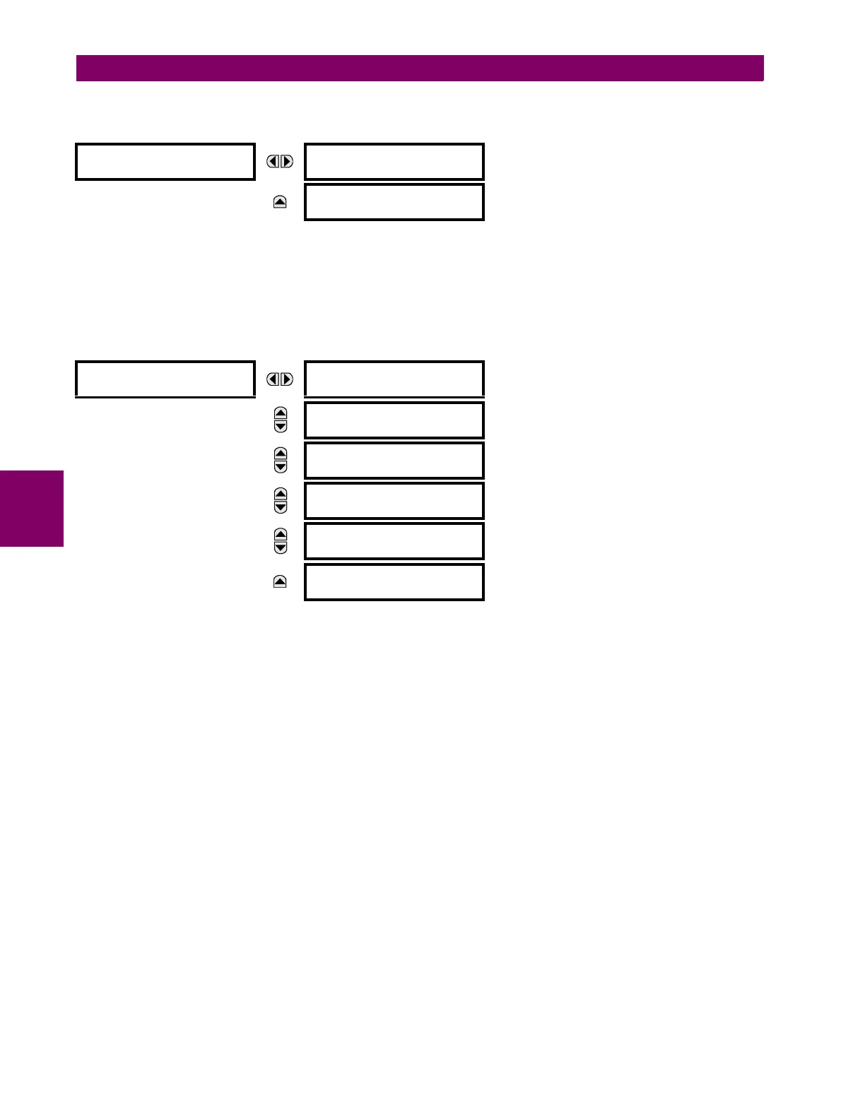
GENERAL
REFERENCE WINDING:
Automatic Selection
Range: Automatic Selection, Winding 1, Winding 2
MESSAGE
PHASE COMPENSATION:
Internal (software)
Range: Internal (software), External (with CTs)
WINDING 1
WINDING 1 SOURCE:
SRC 1
Range: SRC 1, SRC 2, SRC 3, SRC 4
(or the user-defined name)
MESSAGE
WINDING 1 RATED MVA:
100.000 MVA
Range: 0.001 to 2000.000 MVA in steps of 0.001
MESSAGE
WINDING 1 NOM φ-φ
VOLTAGE: 220.000 kV
Range: 0.001 to 2000.000 kV in steps of 0.001
MESSAGE
WINDING 1
CONNECTION: Wye
Range: Wye, Delta, Zig-zag
MESSAGE
WINDING 1 GROUNDING:
Not within zone
Range: Not within zone, Within zone
MESSAGE
WINDING ~ ANGLE WRT
WINDING 1: 0.0°
Range: –359.9 to 0.0° in steps of 0.1, (‘~’ > 1)
(shown when viewed Winding is not Winding 1)