GE Multilin G30 Generator Protection System 5-107
5 SETTINGS 5.4 SYSTEM SETUP
5
This section describes the algorithms in the relay that perform this compensation and produce the required calculated
quantities for transformer differential protection, by means of the following example of a delta-wye (Δ-Y) connected power
transformer with the following data:
The abbreviated nomenclature for applicable relay settings is as follows:
Rotation = SETTINGS SYSTEM SETUP POWER SYSTEM PHASE ROTATION
w
total
= SETTINGS SYSTEM SETUP TRANSFORMER GENERAL NUMBER OF WINDINGS
Compensation = SETTINGS SYSTEM SETUP TRANSFORMER GENERAL PHASE COMPENSATION
Source [w]= SETTINGS SYSTEM SETUP TRANSFORMER WINDING w WINDING w SOURCE
P
rated
[w]= SETTINGS SYSTEM SETUP TRANSFORMER WINDING w WINDING w RATED MVA
V
nominal
[w]= SETTINGS SYSTEM SETUP TRANSFORMER WINDING w WINDING w NOM Φ−Φ VOLTAGE
Connection [w]= SETTINGS SYSTEM SETUP TRANSFORMER WINDING w WINDING w CONNECTION
Grounding [w]= SETTINGS SYSTEM SETUP TRANSFORMER WINDING w WINDING w GROUNDING
Φ[w]= SETTINGS SYSTEM SETUP TRANSFORMER WINDING w WINDING w ANGLE WRT WINDING 1
CT primary
[w] = the phase CT primary associated with Source [w]
Note that w = winding number, 1 to w
total
The following transformer setup rules must be observed:
1. The angle for the first winding from the transformer setup must be 0° and the angles for the following windings must be
entered as negative (lagging) with respect to (WRT) the winding 1 angle.
2. The “Within zone” and “Not within zone” setting values refer to whether the winding is grounded. Select “Within zone” if
a neutral of a wye type winding, or a corner of a delta winding, is grounded within the zone, or whenever a grounding
transformer falls into the zone of protection.
d) PHASE RELATIONSHIPS OF THREE-PHASE TRANSFORMERS
Power transformers that are built in accordance with ANSI and IEC standards are required to identify winding terminals and
phase relationships among the windings of the transformer.
ANSI standard C.37.12.70 requires that the terminal labels include the characters 1, 2, 3 to represent the names of the indi-
vidual phases. The phase relationship among the windings must be shown as a phasor diagram on the nameplate, with the
winding terminals clearly labeled. This standard specifically states that the phase relationships are established for a condi-
tion where the source phase sequence of 1-2-3 is connected to transformer windings labeled 1, 2 and 3 respectively.
IEC standard 60076-1 (1993) states that the terminal markings of the three phases follow national practice. The phase rela-
tionship among the windings is shown as a specified notation on the nameplate, and there may be a phasor diagram. In this
standard the arbitrary labeling of the windings is shown as I, II and III. This standard specifically states that the phase rela-
tionships are established for a condition where a source phase sequence of I-II-III is connected to transformer windings
labeled I, II and III respectively.
The reason the source phase sequence must be stated when describing the winding phase relationships is that these rela-
tionships change when the phase sequence changes. The example shown below shows why this happens, using a trans-
former described in IEC nomenclature as a type “Yd1” or in GE Multilin nomenclature as a “Y/d30.”
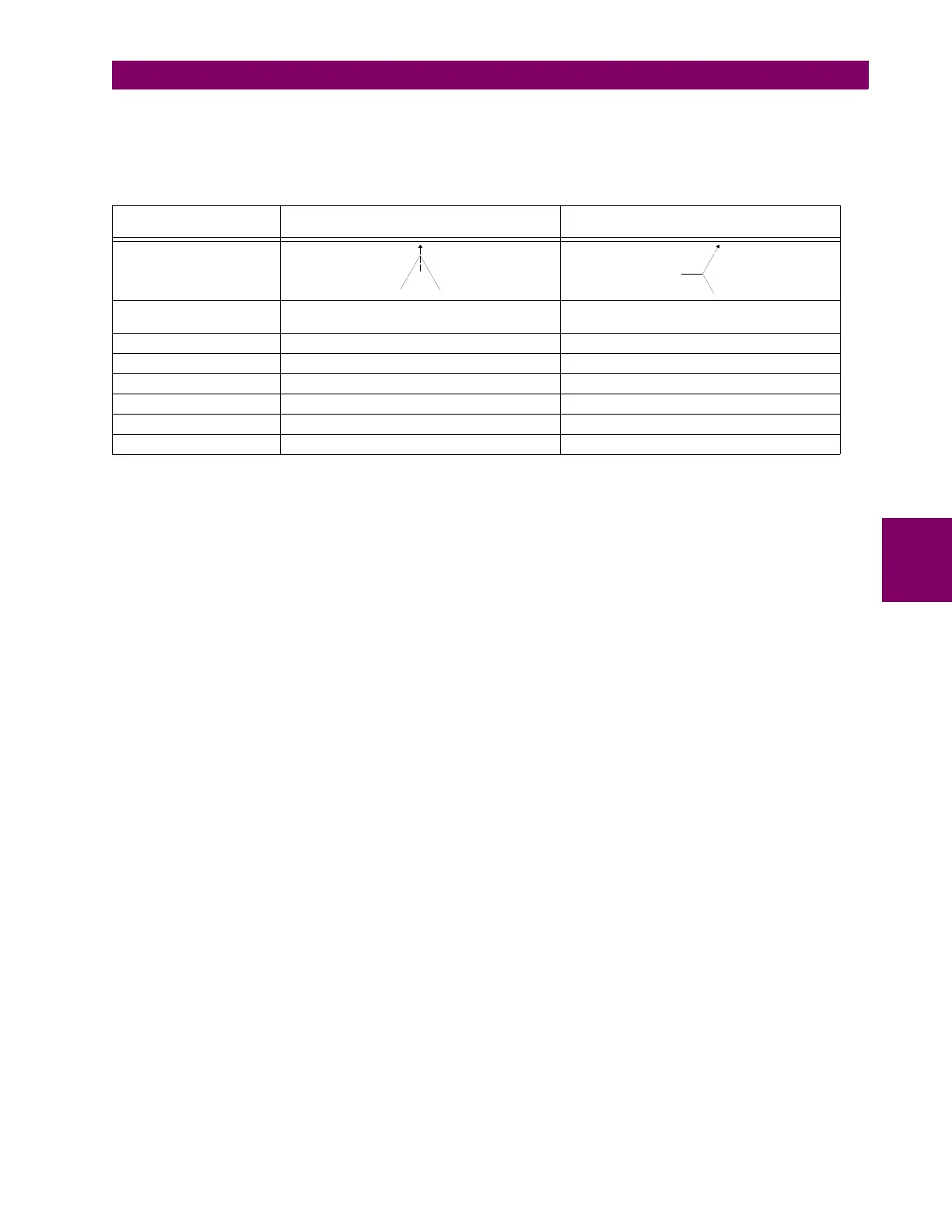
Table 5–13: EXAMPLE DELTA-WYE CONNECTED POWER TRANSFORMER DATA
DATA WINDING 1
Δ (DELTA) CONNECTION
WINDING 2
Y (WYE) CONNECTION
Voltage Phasor Diagram
Phase Shift 0° 30° lag (i.e. phases of wye winding lag
corresponding phases of delta winding by 30°)
Grounding In-zone grounding bank Ungrounded
Rated MVA 100/133/166 MVA 100/133/166 MVA
Nominal φ-φ Voltage 220 kV 69 kV
CT Connection Wye Wye
CT Ratio 500/5 1500/5
Auxiliary Cooling Two stages of forced air Two stages of forced air