– 66 –
Testing points are listed to the right and thermistor
values chart is listed below. Service Mode Test
t4 will display P (Pass), F (Fail), O (Open), or S
(Short) for each thermistor (see Service Mode
Tests in the Service Mode section of this service
guide).
To accurately test a thermistor, place the
thermistor in a glass of ice and water
(approximately 33°F) for several minutes and
check for approximately 16k ohms.
1. Unplug the refrigerator.
2. Access the thermistor.
3. Cut the thermistor wiring as close to the
thermistor as possible.
4. Strip the outer insulation from the thermistor
case harness back 1 inch. Strip the two
internal wires back 3/16 inch for splicing.
5. Prepare the replacement thermistor by cutting
the wiring 4 inches back from the thermistor
and strip the wires back 3/16 inch.
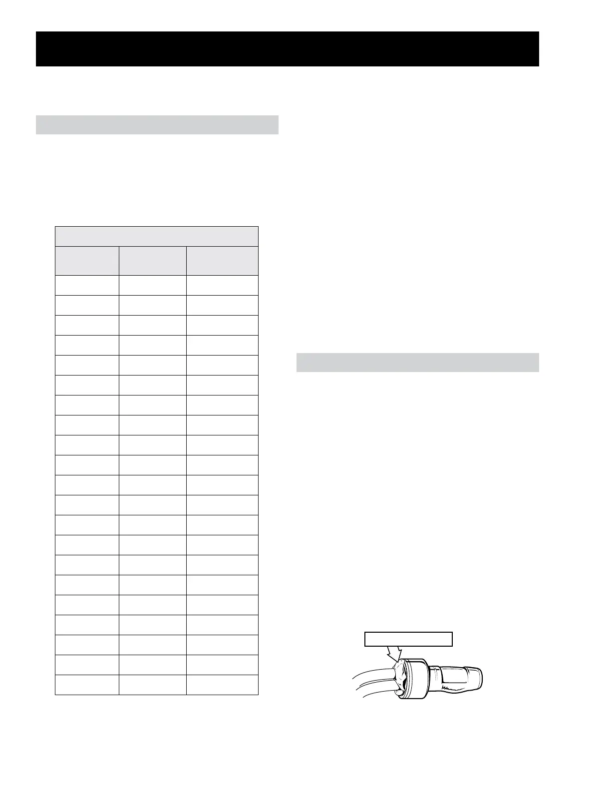
6. Using two bell connectors (Part #:
WR01X10466), splice the wiring. After the
splices are complete, ll the bell connectors
fully with silicone grease (Part #: WR97X163).
7. Reinstall the thermistor into its original
location.
Thermistor Values
Temperature
Degrees (°F)
Temperature
Degrees (°C)
Resistance in
Kilo-Ohms
-40 -40 166.8 kΩ
-31 -35 120.5 kΩ
-22 -30 88 kΩ
-13 -25 65 kΩ
-4 -20 48.4 kΩ
5 -15 36.4 kΩ
14 -10 27.6 kΩ
23 -5 21 kΩ
32 0 16.3 kΩ
41 5 12.7 kΩ
50 10 10 kΩ
59 15 7.8 kΩ
68 20 6.2 kΩ
77 25 5 kΩ
86 30 4 kΩ
95 35 3.2 kΩ
104 40 2.6 kΩ
113 45 2.2 kΩ
122 50 1.8 kΩ
131 55 1.5 kΩ
140 60 1.2 kΩ
FF Thermistor (Main Board)
• J1 pin 1 (white/black) to J1 pin 5/6/8 (red/
white)
FZ Thermistor (Main Board)
• J1 pin 3 (white/blue) to J1 pin 5/6/8 (red/
white)
Ice Box Thermistor (Main Board)
• J14 pin 1 (silver/white) to J5 pin 5 (red/
white)
Evaporator Thermistor (Main Board)
• J1 pin 4 (white/green) to J5 pin 5 (red/white)
Ambient Thermistor (Main Board)
• J1 pin 2 (white/red) to J5 pin 5 (red/white)
The procedure for testing and replacing
thermistors can be found in this section.
Thermistors
Silicone Grease
Thermistor Check Points
Thermistor Replacement
 Loading...