– 76 –
The PTCR Relay/Overload is mounted on the
left side of the compressor and is secured with a
retainer clip. The PTCR relay and overload come
together as an assembly.
PTCR Relay/Overload Diagnosing
The compressor can be turned on using
Service Mode Test t9. Voltage can be checked
at the main board and relay/overload wiring.
Resistance can also be read across the terminals,
if reading open replace the PTCR.
Main Board
• J19 pin 1 (black) to J7 pin 9 (orange): 120
VAC
Overload/Relay Wiring
• Orange to black: 120 VAC
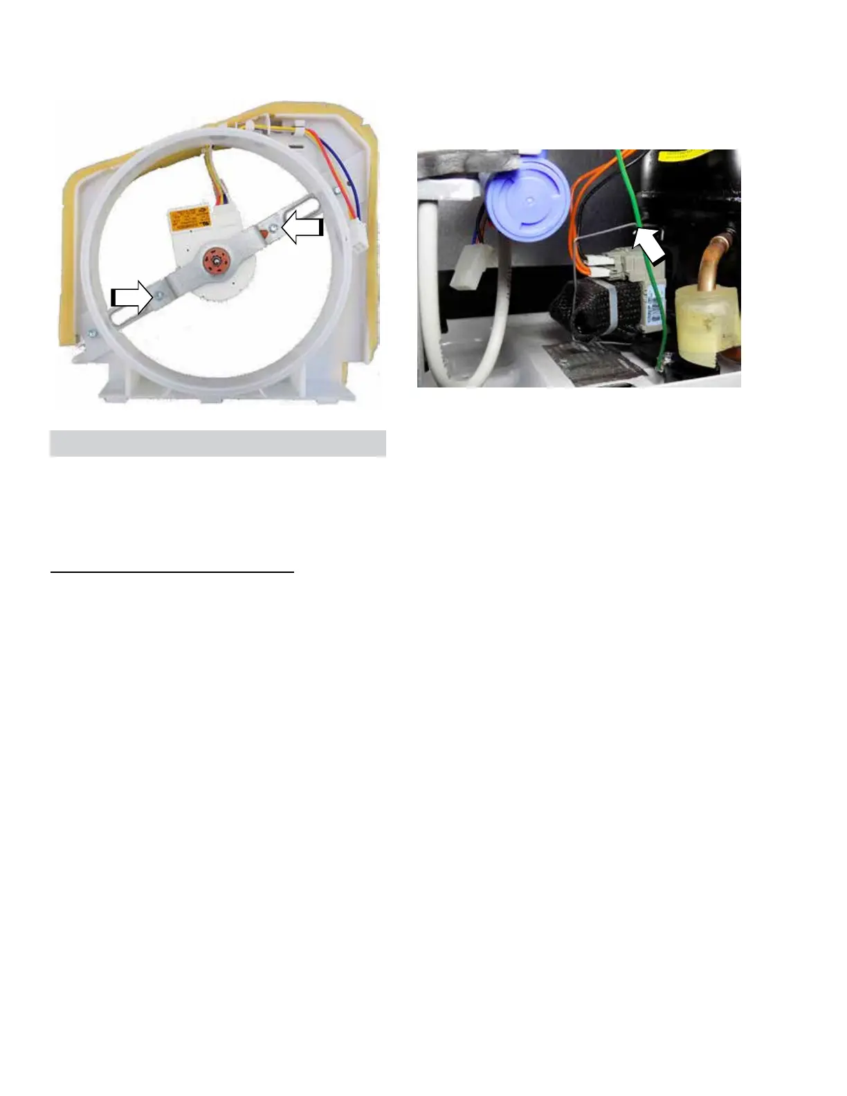
10. Remove two 1/4 in. hex-head screws to
separate the fan motor bracket and remove
the motor from the shroud.
PTCR Relay/Overload Removal
1. Remove the machine compartment cover.
2. Unhook retainer clip securing the PTCR relay/
overload to compressor.
3. Pull PTCR relay/overload straight o
compressor.
CAUTION: Compressor pin damage could result
from prying or pulling o on an angle.
4. Disconnect electrical connectors.
PTCR Relay/Overload