GE Grid Solutions
iBox/iBox Kit
Installation and Maintenance Guide
GE Information
994-0047-5.10-4
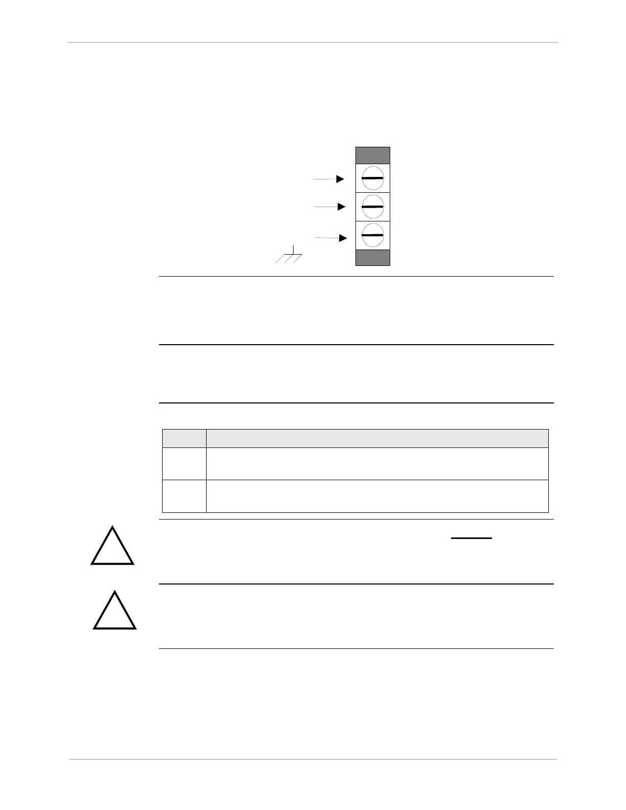
Terminal Connections
Power Supply
The iBox’s power supply connection is a three-position terminal block located on the
bottom left side of the iBox. This removable terminal block must be disconnected to
turn off the power supply input. The iBox does not have an ON/OFF switch.
Functional
Ground/
Chassis
Connect the ground screw terminal to the facility’s ground system before operating
the iBox. Before making this connection, ensure all grounding surfaces are free of
dirt, residue and corrosion. The maximum wire gauge for terminal blocks is 12
AWG.
Internal
Overcurrent
Protection
An internal MDL 0.5 A (slow blow) fuse protects the iBox power supply.
Power
Connection
Procedure
To connect the power source:
Step Action
1
Connect ground wire to the ground terminal. A 12 AWG green and
yellow wire is recommended.
2
Connect the DC power supply, observing the correct polarity, to the
positive and negative connection points on TB1
The chassis ground terminal at the power supply terminal block must not be used as
a protective earth connection.
Make sure the iBox is properly grounded to the protective earth terminal located at
the bottom-left corner of the board. Connection must be provided with a separate
green/yellow wire connected between the iBox and the facility’s ground system.