GE Grid Solutions
iBox/iBox Kit
Installation and Maintenance Guide
GE Information
994-0047-5.10-4
Digital Input Configuration
Digital Input
Field
Connections
Field wiring for all digital input variants are made through the iBox’s terminal
blocks, separable in pairs.
Digital Input
Wetting
Selection
The digital input is wetted (or turned ON) by closing a contact across the two input
termination points. The voltage that is switched at the input terminals is supplied by
an external source. The external power source is connected to terminal block TB-10,
positions 1 and 2, as shown below.
All eight digital inputs are bipolar. Use care when connecting multiple external
power sources, since the digital inputs have common returns.
Wiring
Diagram:
Dry Contact
Operation
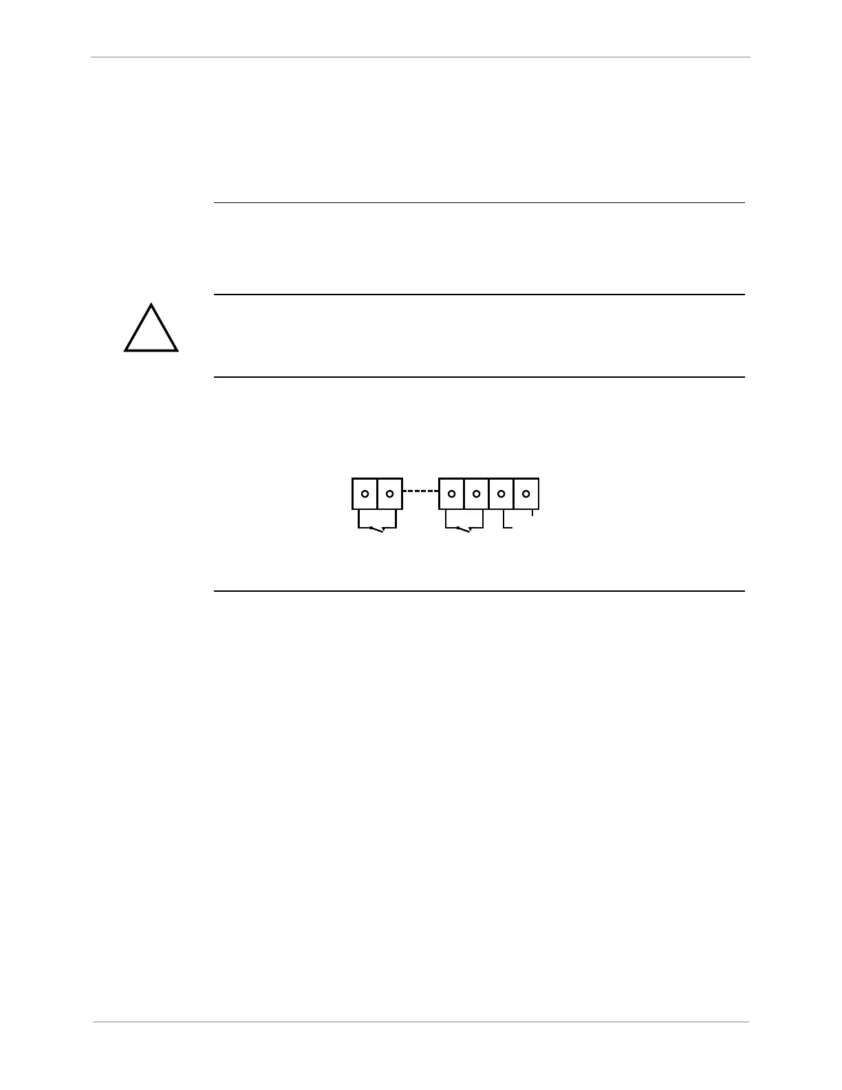
This diagram illustrates the DC input connections, from Input #1 (TB2) through
Input #8 (TB9). TB10 accepts DC voltages of either polarity. The input voltage level
to TB10 is determined by the purchased option.
2
1 1 22 1
Input #1
Input #8
External Wetting
Power Supply
TB2 TB9 TB10
+/- V