iBox/iBox Kit
Installation and Maintenance Guide
GE Grid Solutions
994-0047-5.10-4 GE Information
Digital Outputs
Operating
Modes
iBox control outputs have two modes of operation:
• Trip/Close (T/C) pairs
• Digital Output (DO) isolation Form A contacts.
Note: Using SGConfig, you must configure the digital outputs for four Trip/Close
outputs or two Trip/Close and two digital outputs, depending on the part number.
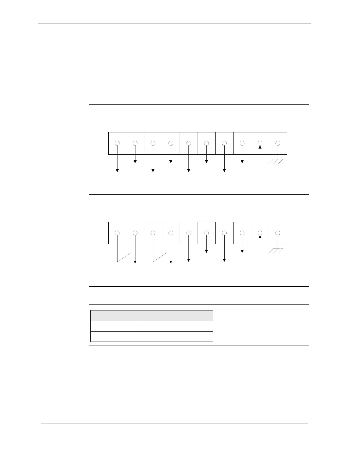
Wiring Four
Trip/Close
Outputs
(Part No.
505-0100,
505-0101,
505-0102)
You can wire four trip/close outputs, as follows:
Wiring Two
Trip/Close
and Two
Digital
Outputs
(Part No.
505-0103,
505-0104,
505-0105)
You can wire two trip/close and two digital outputs, as follows:
Important
iBox digital outputs are not internally fuse-protected.
Remote/Local
Operation
If: Then operation is:
JP2 is installed Remote (controls are enabled)
JP2 is removed Local (controls are disabled)