– 38 –
To remove the control panel assembly on single or
double ovens:
Gain access to the control compartment. (See 1.
Control Compartment Access.)
2. Mark and disconnect the wires from the control
panel assembly.
3. Remove the Phillips-head screw and the ground
wire from the control panel assembly.
To disassemble the GE series control panel:
1. Disconnect and remove the ribbon connector
from the electronic oven control and the key
panel.
2. Remove four ¼-in. hex-head screws that hold
the electronic oven control to the control panel
frame.
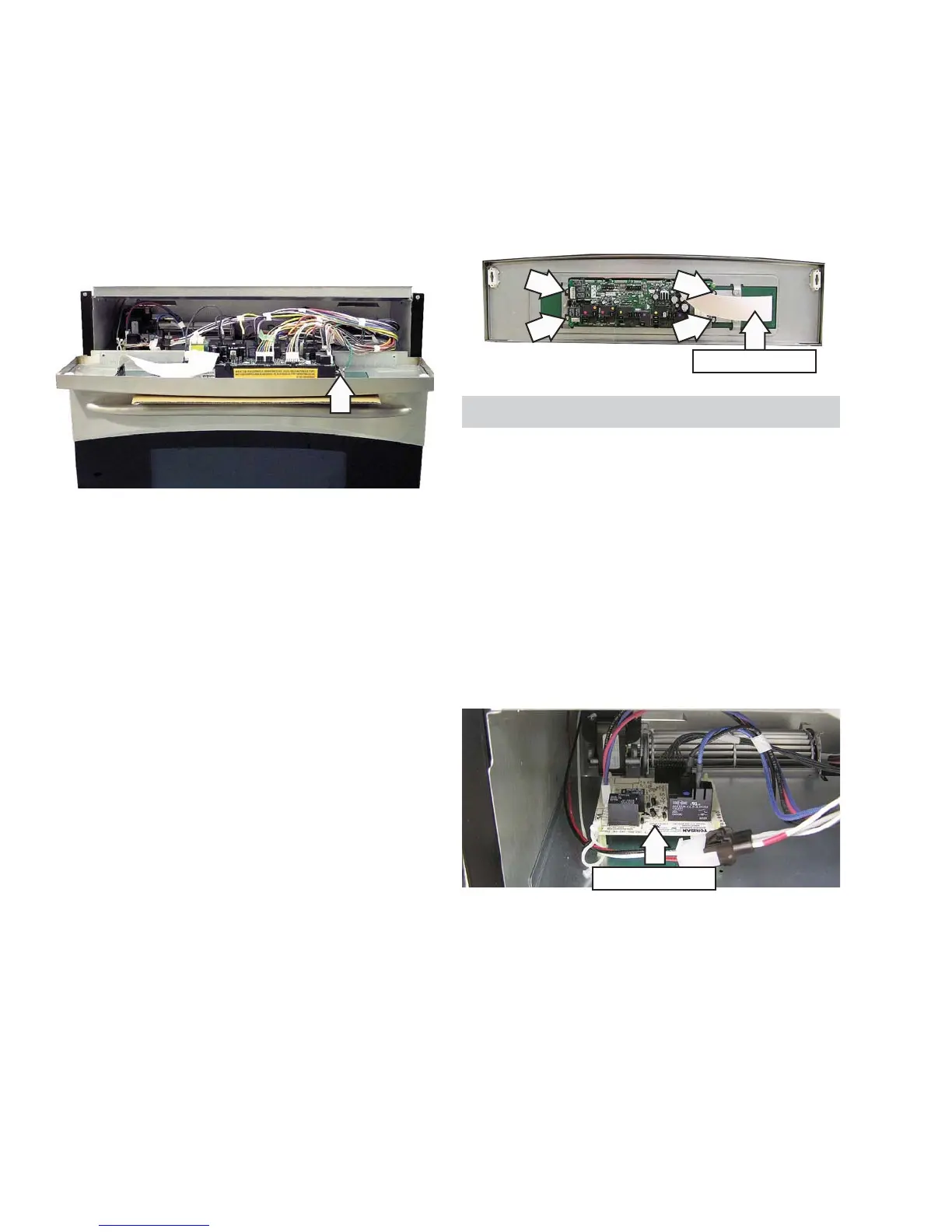
PK916 Series Control Panel Shown
To disassemble the Profi le or Monogram series
control panel:
1. Disconnect and remove the ribbon cable from
the electronic oven control and the key panel.
2. Remove four ¼-in. hex-head screws that hold
the electronic oven control to the control panel
frame.
5. Pull the membrane panel from the key panel.
3. Remove 2 Phillips-head screws from the the
control panel frame.
4. Press in the tabs and remove the key panel from
the control panel frame.
Ribbon Cable
Auxiliary Control Board
The auxiliary control board is only available on
double ovens equipped with convection units.
To remove the auxiliary control board:
Gain access to the control compartment. (See 1.
Control Compartment Access.)
Mark and disconnect all connectors from the 2.
auxiliary board.
Compress the tab on top of each plastic 3.
standoff and then lift the board.
Auxiliary Board
 Loading...