– 39 –
(Continued Next Page)
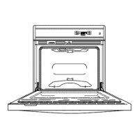
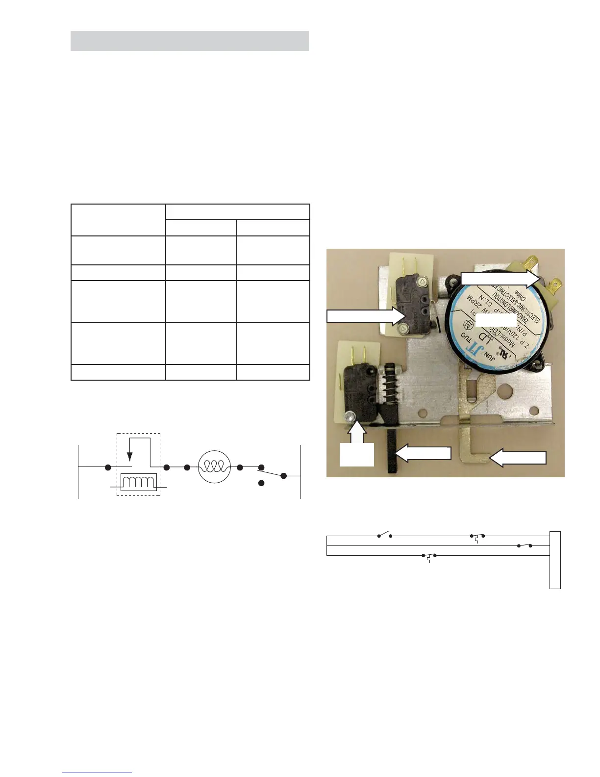
Lock Assembly
The motorized door lock assembly is located above
the oven. The assembly consists of a lock motor
cam and switch assembly, lock hook, mounting
plate, cooling fan switch, spring, plunger, and oven
door switch.
The lock motor is energized when the control is
set for cleaning and a clean time is selected. The
relay contact listed in the chart below will close and
complete the circuit that supplies the voltage to the
lock motor.
The lock motor has an approximate resistance value
of 1.9K Ω.
Note:
To enable proper operation of the door lock, •
ensure that the door jamb switch is in C
"common" to NO "normally open" position (door
closed). This enables power to be delivered when
the door lock closes.
Display of control will fl ash • “LOCKED” if the door
switch is in the C "common" to NC "normally
closed" position (door open).
The word • “LOCKED” will fl ash on and off in the
display while the lock motor is in motion. When
the door is locked, the word “LOCKED” remains
Door Locking/Unlocking Strip Circuit
The cam on the motor performs two functions:
Positions the lock hook in the door to prevent 1.
opening during the cleaning operation.
Operates the lock switches, which tell the 2.
control if the door is unlocked or locked and
ready for the cleaning operation.
Note:3. When the door is either being locked or
unlocked, both the lock and unlock switches will
be in the open position. The locked and unlocked
diagrams are representative of a single or upper
oven but apply to a lower oven as well.
Models
Relay
Upper Oven Lower Oven
JKP30
JKP35
K1 n/a
JKP55 K501 K500
JKP70
PK916
ZEK938
RY660 n/a
JKP75
PK956
ZEK958
K7 K8
JKP90 n/a ?
NC
C
NO
DOOR
SWITCH
N
LOCK
MOTOR
C
MDL
LOCK RELAY
L
O
Y
Y
Y
BUBU
LOCKED
LOCK SW
UNLOCK SW
1
2
3
4
5
6
HIGH TEMP
THERMAL SW
LOW TEMP
THERMAL SW
Door Lock - Locked Position
Strip Circuit
Motor
Door
Switch
Hook
Plunger
Unlock Switch
Lock Switch
 Loading...