– 40 –
(Continued Next Page)
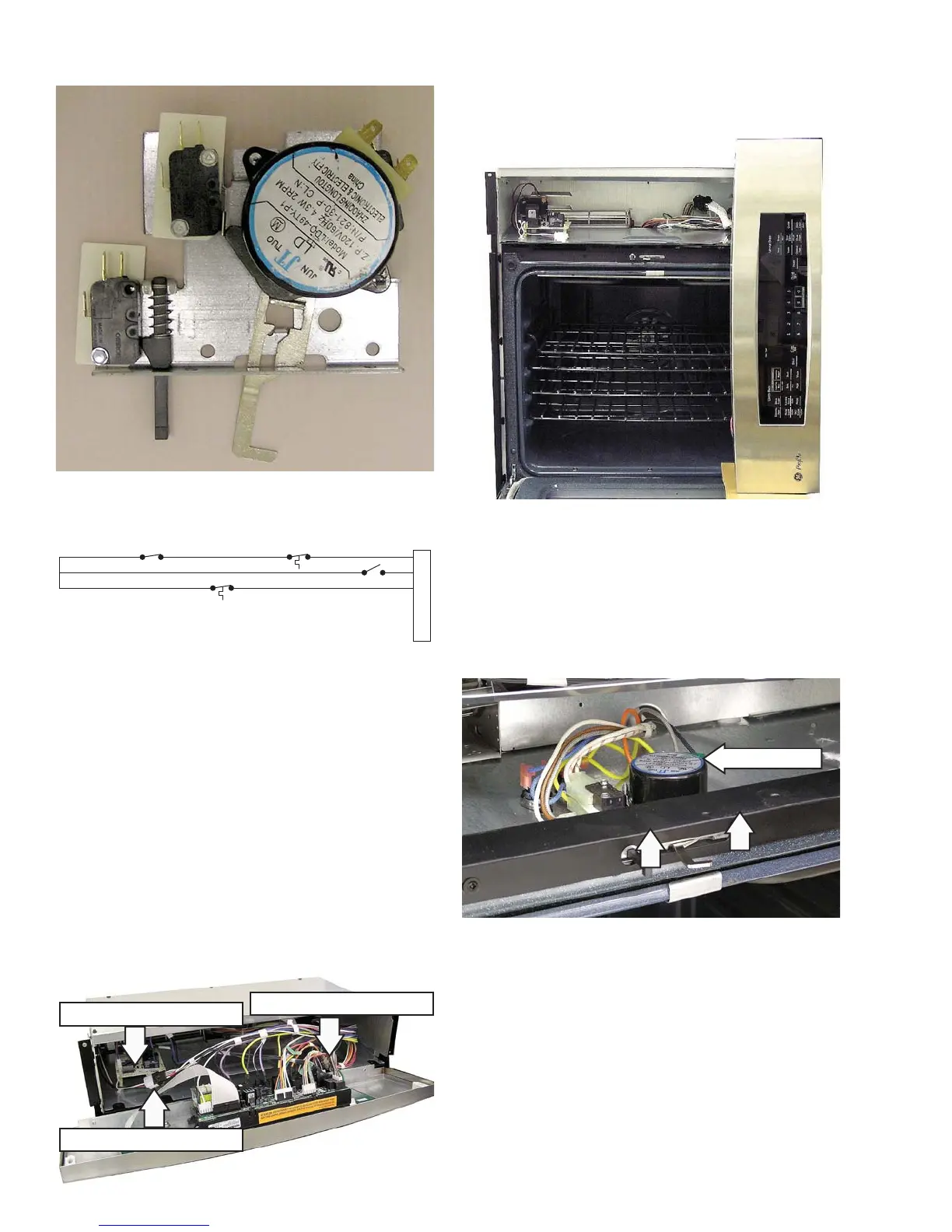
Door Lock - Unlocked Position
Strip Circuit
To remove the lock assembly on single and upper
double ovens:
Gain access to the control compartment. (See 1.
Access Control Compartment.)
Mark and disconnect the cooling fan connector.2.
Mark and disconnect the light housing 3.
connector.
On double ovens, mark and disconnect all 4.
connectors on the auxiliary control board, if
equipped.
Caution: It is possible to reconnect the switch wiring
incorrectly to the lock assembly. When reconnecting
the wiring, make sure it is properly connected to the
lock assembly before turning the power back on.
O
Y
Y
Y
BUBU
UNLOCKED
LOCK SW
UNLOCK SW
1
2
3
4
5
6
HIGH TEMP
THERMAL SW
LOW TEMP
THERMAL SW
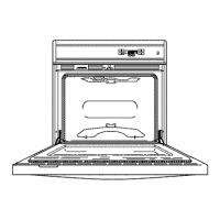
Hold the control panel and open the oven door.5.
Place the control panel on the protected oven 6.
door as shown.
Auxiliary Control Board
Cooling Fan Connector
Light Housing Connector
Lift the metal air divider.7.
Mark and disconnect the connectors from the 8.
lock assembly.
Remove 2 Phillips-head screws and the lock 9.
assembly from the oven.
Lock Assembly
 Loading...