– 54 –
Oven Sensor and Door Switch Test
Note: See Lock Assembly for an explanation of the door switch function.
Remove power from the oven. 1.
Make resistance measurements from the side of the sensor and the lock switch connector with exposed 2.
terminals.
The resistance measurements are made on the logic board at the connector listed on the chart below.3.
If an abnormal reading is observed, wiggle the leads at the disconnect block. If there is any variation, 4.
replace the component.
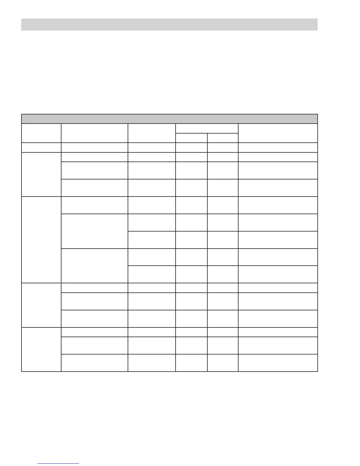
Resistance Measurement Chart
Models Circuit Connector
Terminals
Ohms
Upper Lower
JKS10 Oven Sensor CN2 4 to 6 n/a 1080 Ω @ Rm. Temp.
JKP30
JKP35
Oven Sensor CN2 4 to 6 n/a 1080 Ω @ Rm. Temp.
Door Unlatched
CN2 1 to 3
2 to 3
n/a 0 Ω
open
Door Latched
CN2 2 to 3
1 to 2
n/a 0 Ω
open
JKP55
JKP75
PK956
ZEK958
Oven Sensor
J3 (upper)
J4 (lower)
6 to 8
1 to 2
1080 Ω @ Rm. Temp.
Door Unlatched
J3 (upper) 3 to 5
4 to 5
0 Ω
open
J4 (lower) 4 to 6
4 to 5
0 Ω
open
Door Latched
J3 (upper) 4 to 5
3 to 5
0 Ω
open
J4 (lower) 4 to 5
4 to 6
0 Ω
open
JKP70
PK916
ZEK938
Oven Sensor CN2 6 to 8 n/a 1080 Ω @ Rm. Temp.
Door Unlatched
CN2 3 to 5
4 to 5
n/a 0 Ω
open
Door Latched
CN2 4 to 5
3 to 5
n/a 0 Ω
open
JKP90 Oven Sensor J1 4 to 6 n/a 1080 Ω @ Rm. Temp.
Door Unlatched
CN2 1 to 3
2 to 3
n/a 0 Ω
open
Door Latched
CN2 2 to 3
1 to 3
n/a 0 Ω
open
 Loading...