Chapter 2: Installation
Kilsen KFP-CF Series Installation Manual 9
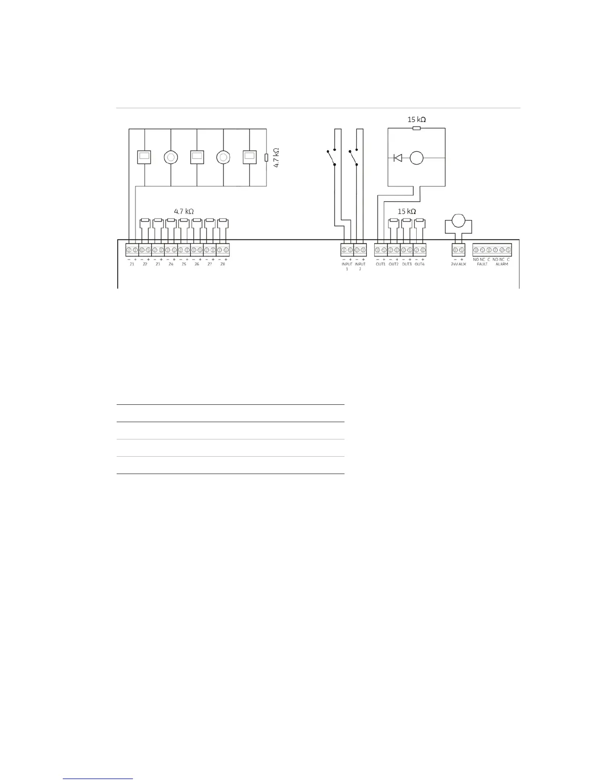
Overview of fire system connections
Figure 4: Overview of fire system connections
Connecting zones and zone devices
Connecting zones
Connect zone wires as shown in Figure 4 above. Line resistance is shown in the table
below.
Zone type Line resistance
Mixed (automatic and manual) Max. 40 Ω
Automatic Max. 55 Ω
Manual Max. 55 Ω
Note: The default zone detection settings for each operating mode can be found in
Appendix A “Configuration presets” on page 59. To change the zone detection setting,
see “Advanced configuration” on page 31.
Terminating zones
Each zone circuit requires a 4.7 kΩ end-of-line resistor for termination. If a zone is not
used, the 4.7 kΩ end-of-line resistor must be installed across the unused zone
terminals.
Note: For BS 5839-1 the default zone configuration is active end-of-line and an active
end-of-line module must be installed instead of an end-of-line resistor. Unused zones
must be terminated with an active end-of-line module or configured as passive end-
of-line and terminated with a 4.7 kΩ end-of-line resistor as described above.
 Loading...