892829A1.cdr
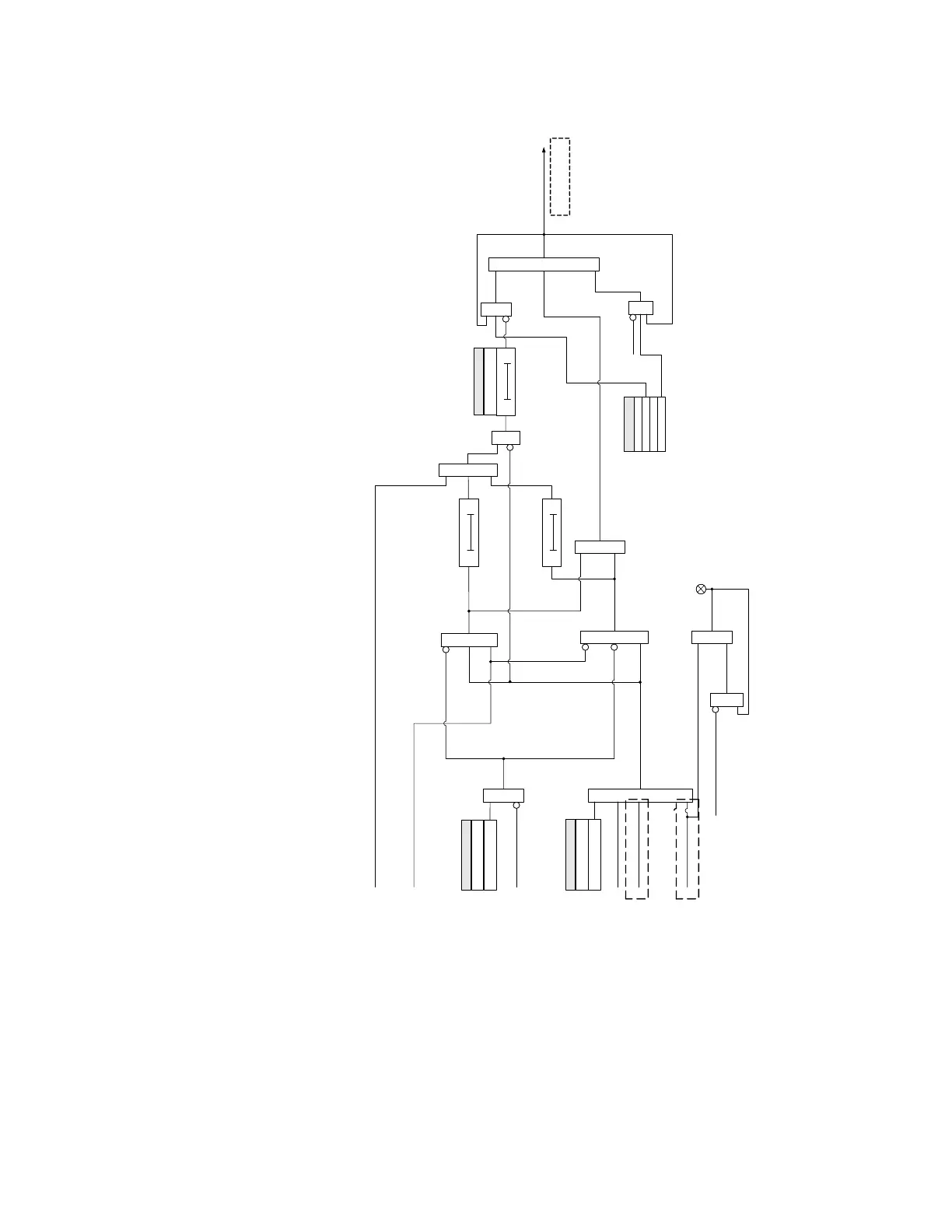
Trip request
At least one
contact programmed
(from Breaker Detection)
AND
OR
TRIP
Trip without
configured
breaker contact
OR
AND
AND
AND
TRIP
Operate Output
Relay 1 “TRIP”
OR
Relay ( Ready = 1)
LED: TRIP
AND
OR
Trip when at least
one breaker
contact configured
OR
SEAL-IN TIME
SETPOINT
2 sec
This timer starts on the falling edge
of a pulse, and issues a positive
pulse upon time expiry
t
RESET (command)
Relay ( Ready = 1)
OR
BLOCK
SETTING
Off = 0
100 ms
TRIP ( from Any Element set to “Trip” )
OPEN ( from Breaker Control )
OPEN ( from Transfer Scheme)
This timer starts on the falling edge of
a pulse, and issues a positive pulse
upon time expiry
Upon dropout of the trip signal and no
breaker open status detected, this timer
will start on the raising edge of a pulse
issued from either of the two timers, and
will produce positive pulse upon time
expiry.
When breaker open status is detected,
and no trip is present, the output relay
will stay reset.
AND
TYPE
SETPOINT
Pulsed
Self-Reset
RESET (command)
For 850 only
Latched
Relay ( Ready = 1)
OPERATE
SETTING
FL Operand, Off = 0
For 850, 869, and 889 only
For 850, 869, and 889 only

 Loading...


