3–6 869 MOTOR PROTECTION SYSTEM – INSTRUCTION MANUAL
FRONT CONTROL PANEL INTERFACE CHAPTER 3: INTERFACES
To change/view an item on from the 869 menus:
1. Use the pushbuttons that correspond to the tabs (Targets, Status, Metering, Setpoints,
Recor
ds) on the screen to select a menu.
2. Use the Up and Down pushbuttons to highlight an item.
3. Press Enter to view a list of values for the chosen item. (Some items are view-only.)
4. Use the Up and Down pushbuttons to highlight a value.
5. Press Enter to assign the highlighted value to the item.
Single Line Diagram
BKR1 LED setting for Breaker symbol color configuration
In all 8 Series devices the breaker symbol color is configurable through the first LED
assi
gned to operate with the BKR 1 Open operand.
Single Line Diagram for 869
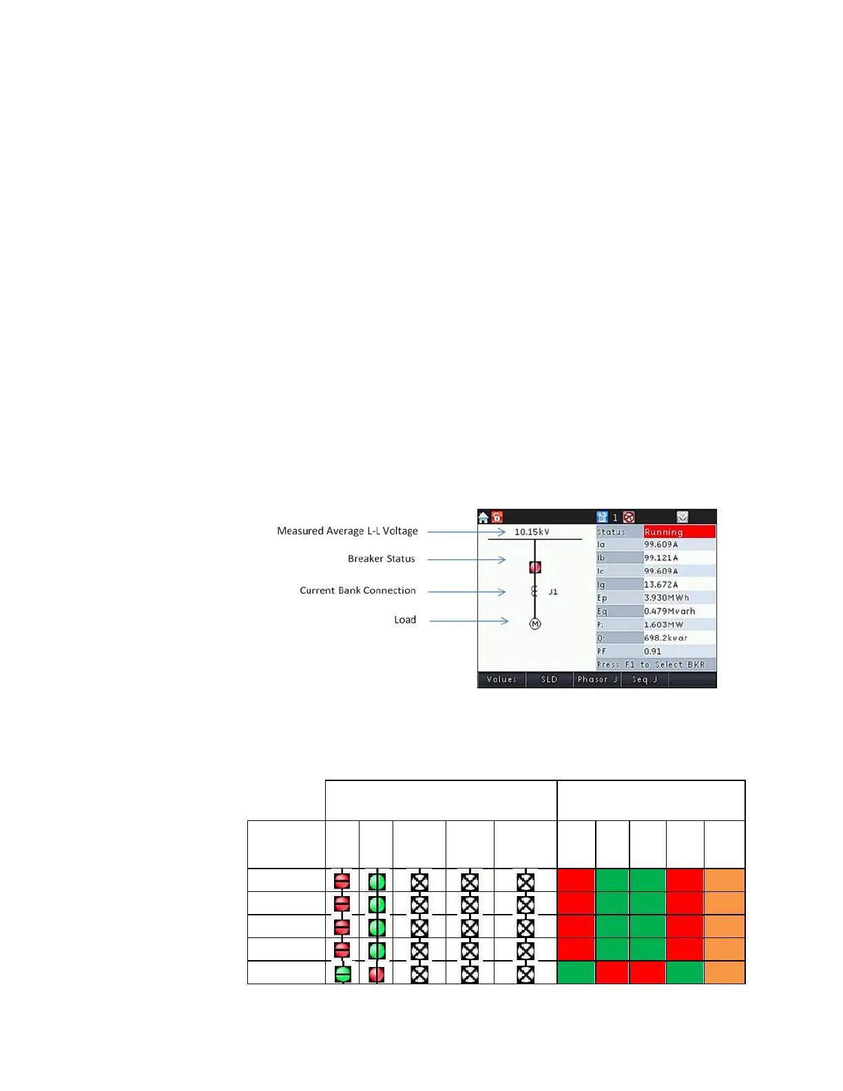
The 869 has a single line diagram (SLD) that repre
sents the power system. The single line
diagram provided is pre-configured to show:
• Breaker status
• AC input connection
• System voltage
Accompanying the single line diagram are typical metered values associated with the
power syst
em.
The single line diagram is configured as the default menu but this can
be changed under
Setpoints > Device > Front Panel > Default Screen.
Figure 3-6: SLD and typical metered values screen
The breaker status icon changes state according to the breaker status input and the color
of the icon cha
nges in accordance with the LED color setting.
The breaker status and motor status is based on the following logic.
Figure 3-7: Breaker/Contactor and Motor status color
SLD Breaker/Contactor Symbol Color Motor Status
BKR1/Contactor
Open LED
Open
Color
Close
Color
Not
Configured
Unknown Disconnected Stopped
Starting
Tripped
Not Assigned
Red Green Green Red Orange
OFF
Red Green Green Red Orange
Orange
Red Green Green Red Orange
Red
Red Green Green Red Orange
Green
Green Red Red Green Orange