CHAPTER 4: SETPOINTS OUTPUTS
869 MOTOR PROTECTION SYSTEM – INSTRUCTION MANUAL 4–101
Analog Outputs
Description
Depending on the order code, the 8 Series relay supports one optional DC analog card. The
Ana
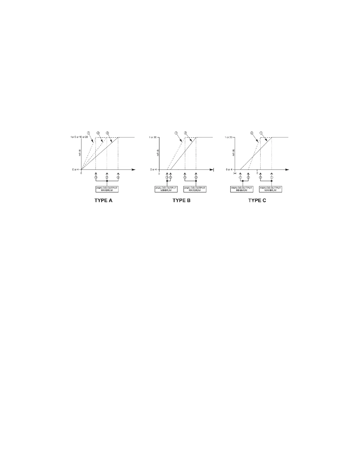
log card has 4 analog inputs and 7 analog outputs. There are three Analog Output
channel scenarios for analog minimum and maximum output range: A, B, and C shown in
the figure below. Type A characteristics apply when the minimum range is 0 and the
maximum range is a positive (+ve) value. Type B characteristics apply when the minimum
and maximum ranges are definitely positive (+ve) values. Type C characteristics apply
when the minimum range is a negative (-ve) and the maximum range is a positive (+ve)
value. The following diagram illustrates these characteristics.
Figure 4-26: Analog Outputs Channel Characteristics
Path:
Setpoints > Outputs > Analog Outputs > Analog Output 1(X)
Settings
FUNCTION
Range: Disabled, Enabled
Default: Disabled
RANGE
Range: 0 to 1 mA, 0 to 5 mA, 0 to 10 mA, 0 to 20 mA, or 4 to 20 mA
Default: 0 to 1 mA
This setting provides the selection for the analog output range.
PARAMETER
Range: Off, any Flex Analog Parameter
Default: Off
This setting selects the measured parameter to control the Analog Output level.
MINIMUM VALUE
Range: Populates per selection of the analog parameter
Default: 0
This setting defines the minimum value of the analog output quantity. It populates
based on the selection of the analog parameter.