4–240 869 MOTOR PROTECTION SYSTEM – INSTRUCTION MANUAL
PROTECTION CHAPTER 4: SETPOINTS
Power Elements
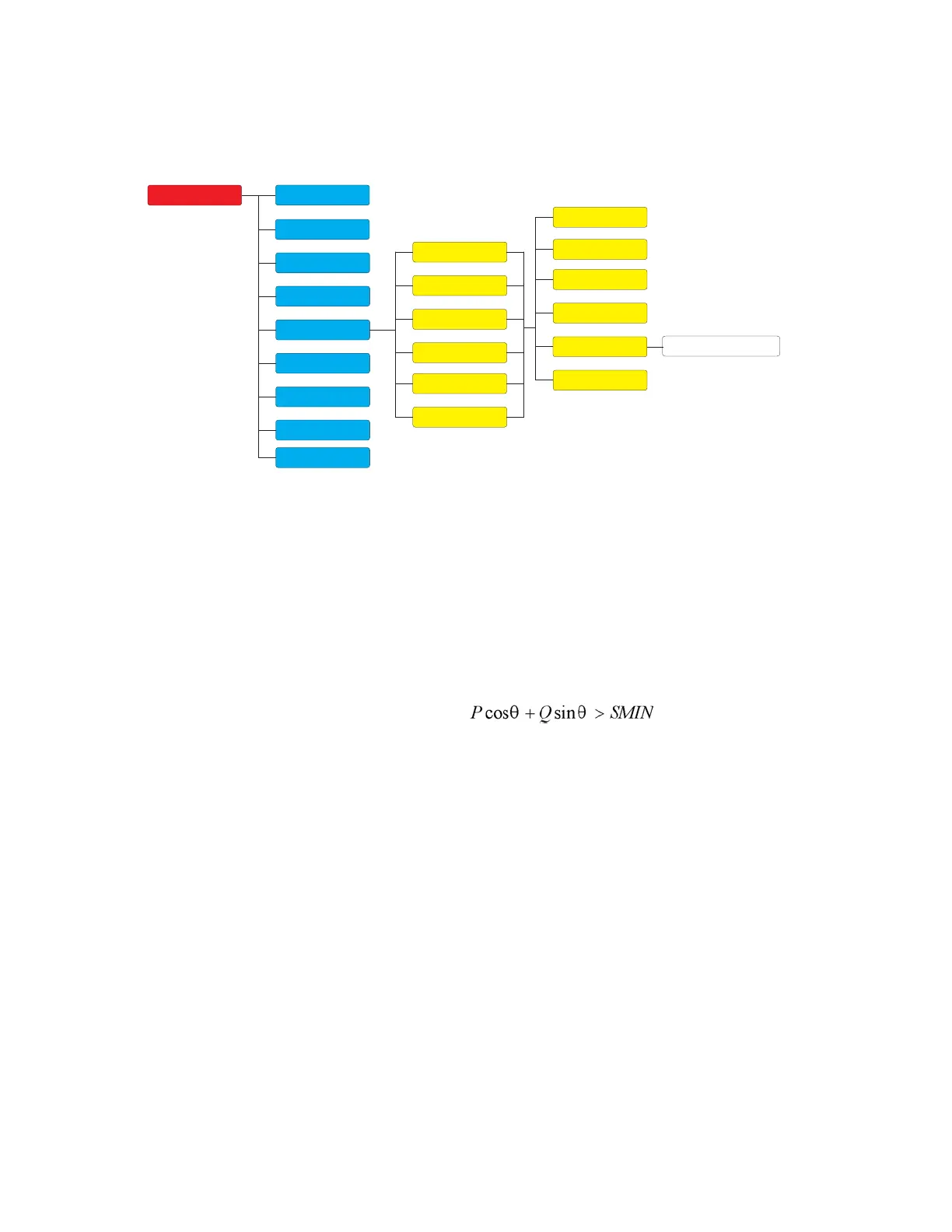
Figure 4-87: Power Elements Display Hierarchy
Directional Power
The 869 relay provides two identical Directional Power elements per protection group; a
total of 12 elements.
The Directional Power element responds to three-phase directional power and is designed
for
reverse power (32REV) and low forward power (32FWD) applications for synchronous
machines or interconnections involving co-generation. The relay measures the three-
phase power from either a full set of wye-connected VTs or a full-set of delta-connected
VTs. In the latter case, the two-wattmeter method is used.
The element has an adjustable characteristic angle and minimum operating power as
show
n in the Directional Power characteristic diagram. The element responds to the
following condition:
Where:
P and Q are active and reactive powers as measured per the metering convention
Ɵ
is a sum of the element characteristic (DIR POWER 1 RCA) and calibration (DIR
POWER 1 CALIBRATION) angles
SMIN is the minimum operating power.
The element has two independent (as to the Pickup and Delay settings) stages for Alarm
and Trip
, and they can be set separately to provide mixed power protection.
2-Speed Motor
Setpoints
Device
System
Inputs
Outputs
Protection
Monitoring
Control
FlexLogic
Data Capture
Power
Frequency
Voltage
Current
Directional Power
Group 1
Group 2
Group 3
Group 4
Group 5
Group 6
Motor
Testing
 Loading...


