It can be seen that:
● The voltage in the faulty phase r
educes to almost 0V
●
The healthy phases raise their phase to earth voltages by a factor of Ö3
● The triangle of voltages remains balanced
● The charging currents lead the voltages by 90°
Using a core-balance current transformer (CBCT), the current imbalances on the healthy feeders can be measured.
They correspond to simple vector addition of I
A1
and I
B1
, I
A2
and I
B2
, I
A3
and I
B3
, and they lag the residual voltage
by exactly 90º.
The magnitude of the residual current I
R1
is equal to three times the steady-state charging current per phase. On
the faulted feeder, the residual current is equal to I
L
- I
H1
- I
H2
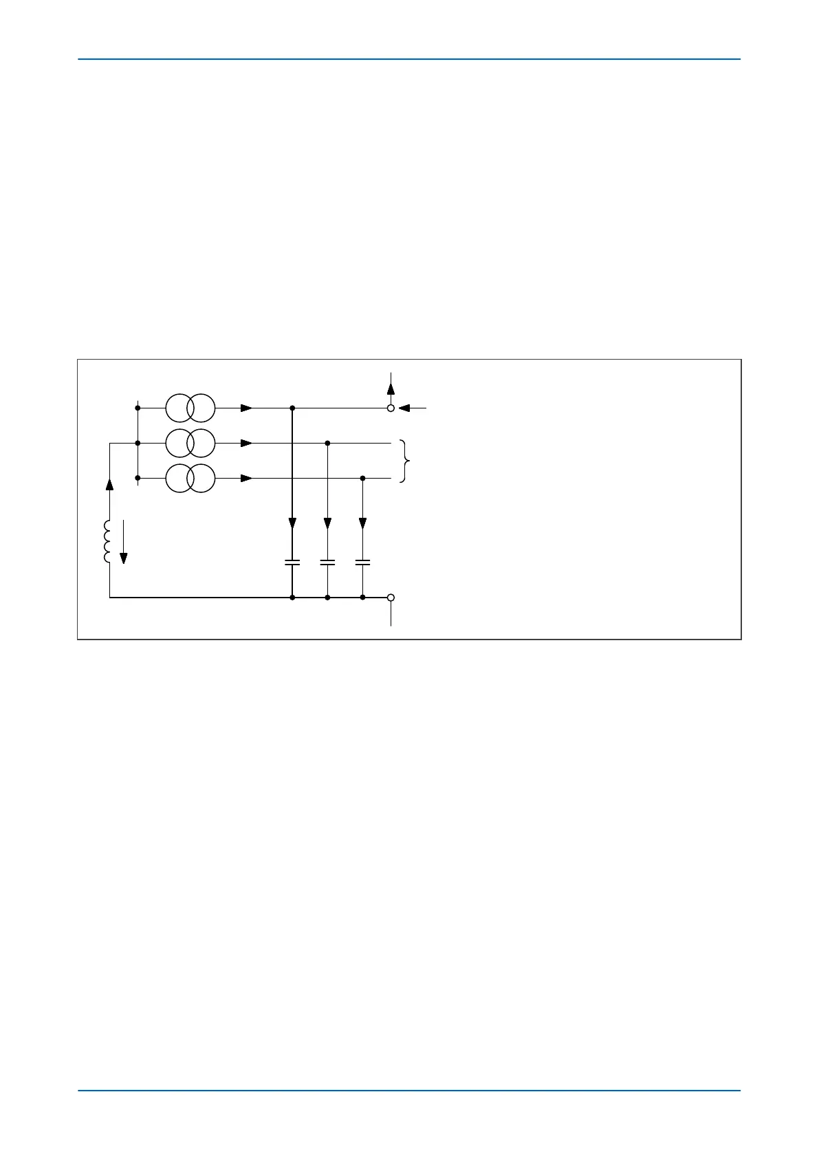
(C). This is shown in the zero sequence network
shown in the following figure:
V00640
I
ROF
= Residual current on faulted feeder
I
ROH
= Residual current on healthy feeder
IOF = IL – IH1 – IH2 – IH3
I
ROF
= I
H3
+ I
OF
so:
I
ROF
= I
L
– I
H1
– I
H2
3X
L
I
L
-V
0
X
CO
IH3 IH2 IH1
Healthy feeders
Faulty feeder
I
ROF
I
ROH
I
ROH
I
OF
Figure 56: Zero sequence network showing residual currents
In practical cases, however, resistance is present, resulting in the following phasor diagrams:
P14x Chapter 6 - Current Protection Functions
P14xEd1-TM-EN-1 127
 Loading...


