Wiring Diagram (P141, P142, P143, P145)
P141, P142, P143, P145
C19
C22
C17
C18
E00824
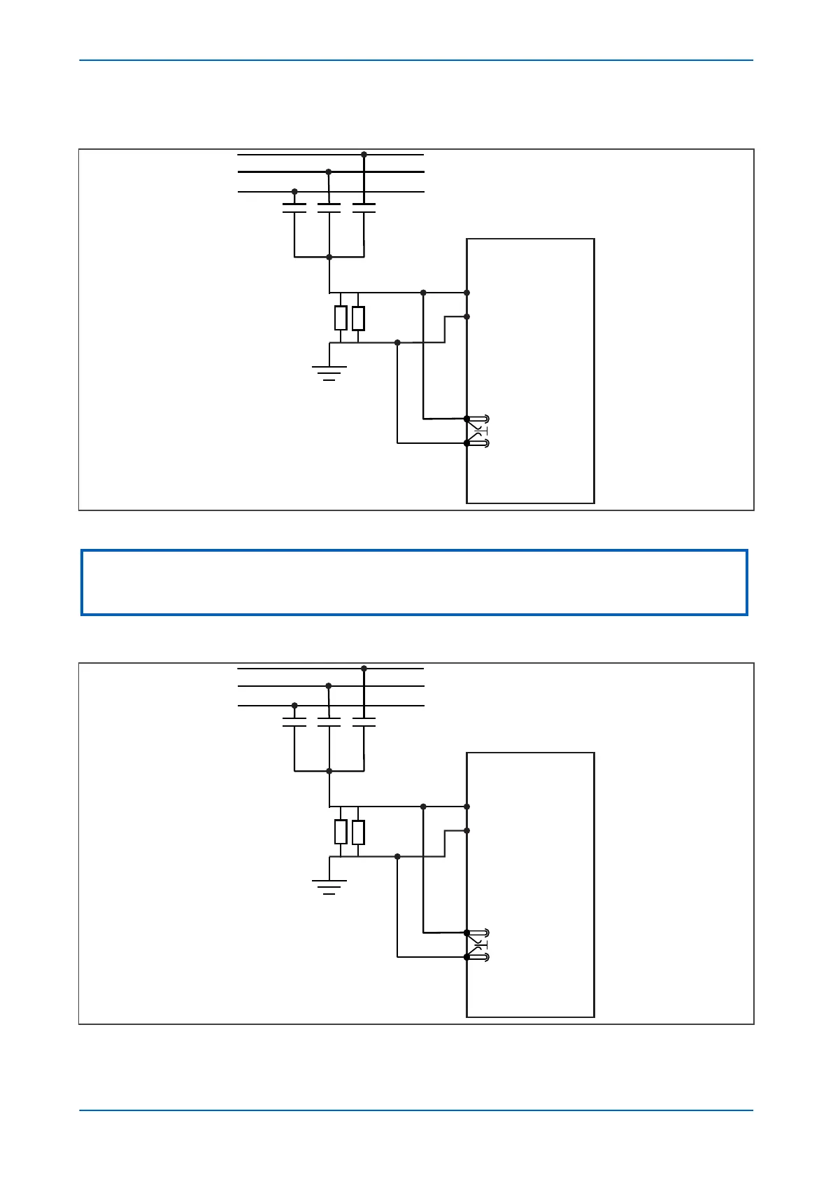
Figure 120: Device connection P141/ P142/ P143/ P145
Note:
R
esidual voltage measurement is derived from phase inputs, but neutral voltage may be connected into one of the phase
inputs. This assumes that voltage inputs are not used for other purposes
Wiring Diagram (P144)
Figure 121: Device connection P144
Chapter 10 - Voltage Protection Functions P14x
226 P14xEd1-TM-EN-1
 Loading...


