This is a communications board that provides a standard 100-Base Ethernet interface. This board supports one
electrical copper connection and one fibre-pair connection.
Ther
e are several variants for this board as follows:
● 100 Mbps Ethernet board
● 100 Mbps Ethernet with on-board modulated IRIG-B input
● 100 Mbps Ethernet with on-board unmodulated IRIG-B input
Two of the variants provide an IRIG-B interface. IRIG-B provides a timing reference for the unit – one board for
modulated IRIG-B and one for demodulated. The IRIG B signal is connected to the board with a BNC connector.
The Ethernet and other connection details are described below:
IRIG-B Connector
● Centre connection: Signal
● Outer connection: Earth
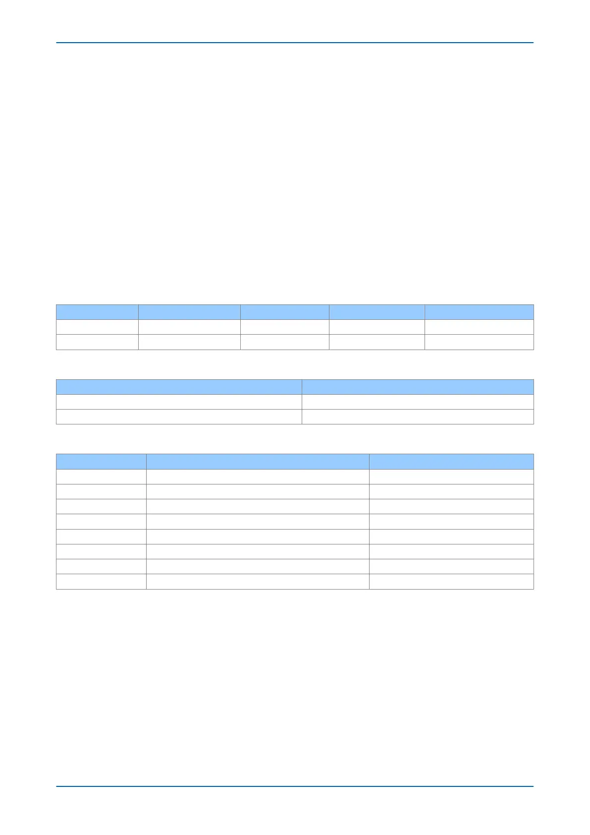
LEDs
LED Function On Off Flashing
Green Link Link ok Link broken
Yellow Activity Traffic
Optical Fibre Connectors
Connector Function
Rx Receive
Tx Transmit
RJ45connector
Pin Signal name Signal definition
1 TXP Transmit (positive)
2 TXN Transmit (negative)
3 RXP Receive (positive)
4 - Not used
5 - Not used
6 RXN Receive (negative)
7 - Not used
8 - Not used
P14x Chapter 3 - Hardware Design
P14xEd1-TM-EN-1 53
 Loading...


