2 MM200 MOTOR MANAGEMENT SYSTEM – QUICK START GUIDE
CAUTIONS AND WARNINGS CHAPTER 1: OVERVIEW
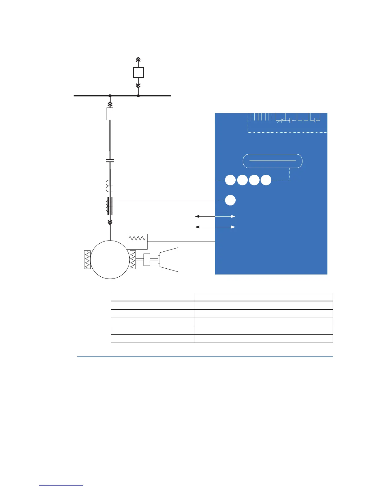
Figure 1-1: Single line diagram
Table 1-1: MM200 protection functions
Cautions and Warnings
Before attempting to install or use the device, review all safety indicators in this document
to help prevent injury, equipment damage, or downtime.
Safety words and definitions
The following symbols used in this document indicate the following conditions
RS485 - Modbus RTU
Profibus/DeviceNet
52
METERING
A
51R
49
37
46
50G
MOTOR
LOAD
Temperature
Thermistor
Phase CT 3
Ground CT 1
Power Fuse
BUS
MM200
MOTOR MANAGEMENT SYSTEM
Contactor
888739A2.CDR
LO: 7 inputs and 3 outputs
HI: 6 inputs and 3 outputs
LO:24VDC
HI:84to250VDC/60to300VAC
ANSI device Description
37 Undercurrent and underpower
46 Current unbalance
49 Thermal overload
50G Ground instantaneous overcurrent
51R Locked/stalled rotor, mechanical jam
 Loading...


