12 MM200 MOTOR MANAGEMENT SYSTEM – QUICK START GUIDE
ELECTRICAL INSTALLATION CHAPTER 2: INSTALLATION
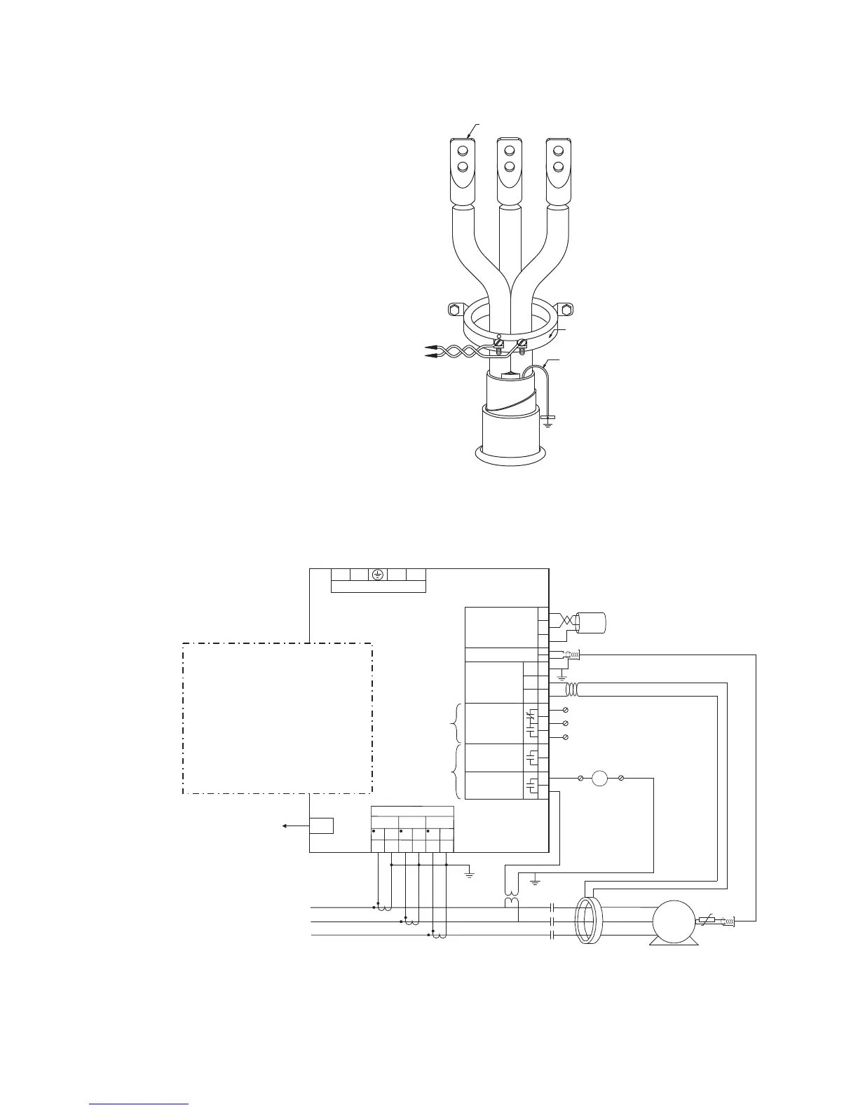
Figure 2-11: Core balance ground CT installation, unshielded cable
Full-voltage non-reversing starter
Figure 2-12: Full-voltage non-reversing starter wiring
POWER CABLE
TO MOTOR
50:0.025 CORE BALANCE CT
FOR GROUND CT SENSING
TO STARTER
GROUND BUS
CABLE LUGS TO SOURCE
TERMINATION
(TWISTED-PAIR)
888713A1.CDR
GROUND CONDUCTOR DOES
NOT PASS THROUGH CT, AS THE
CT IS NOT MOUNTED OVER
GROUND WITHIN THE CABLE
JACKET.
BOTTOM OF
MOTOR STARTER
COMPARTMENT
CORE BALANCE CT
SECONDARY CONNECTION
TO MM200 IED
888741A3.CDR
A
C
B
Contactor
Contactor
TO
CONTROL
PANEL
C1
C2
C4
C3
C5
C6
MM200
Motor Management System
C8
C9
C10
C7
Two form-A
contact outputs
CONTACT OUTPUT 2
One form-C
contact output
CONTACT OUTPUT 1
CONTACT OUTPUT 3
THERMISTOR
CBCT
RS485
R
I
-
+
-
+
C
B3
B4
B5
B6
B7
B8
I
R
I
R
I
R
CT1
CT2
CT3
CT MODULE
RJ45
PROFIBUS OR DEVICENET
V-
L
H
V+
MOTOR
M
M
SG
LO and HI inputs
- see below -

 Loading...


