8 MM200 MOTOR MANAGEMENT SYSTEM – QUICK START GUIDE
ELECTRICAL INSTALLATION CHAPTER 2: INSTALLATION
Electrical installation
This section describes the electrical installation of the MM200 system. An overview of the
MM200 terminal connections is shown below.
CAUTION:
MM200 is not to be used in any way other than described in this manual.
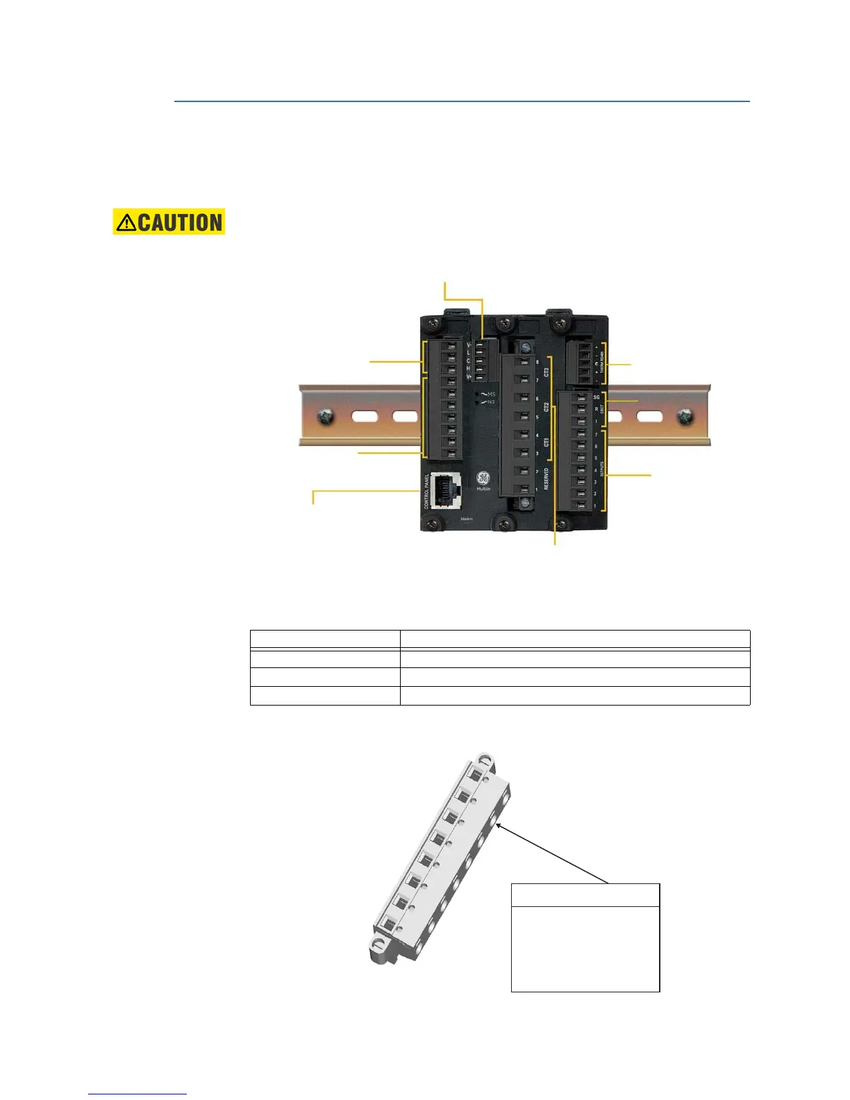
Figure 2-5: MM200 terminal connection overview
A Modbus RTU RS485 port, a thermistor input, and a 50:0.025 CBCT input are provided.
Profibus and Devicenet are provided as options.
Table 2-1: Slot position
Figure 2-6: MM200 terminal connection torque rating
Slot Type
A PSU/Inputs/Control Panel
BCPU/CTs
C Outputs/CBCT/Thermistor/RS485
Control Panel
Profibus or DeviceNet
Optional fieldbus protocols
888740A2.CDR
CTs
PSU
Inputs
RS485
Thermistor
CBCT
2 x Form A
1 x Form C
connector screw torque
CT 4.5 lb-in
IPS, output 5.0 lb-in
Fieldbus, 3.0 lb-in
Thermistor & RS485

 Loading...


