CHAPTER 2: INSTALLATION ELECTRICAL INSTALLATION
MM200 MOTOR MANAGEMENT SYSTEM – QUICK START GUIDE 11
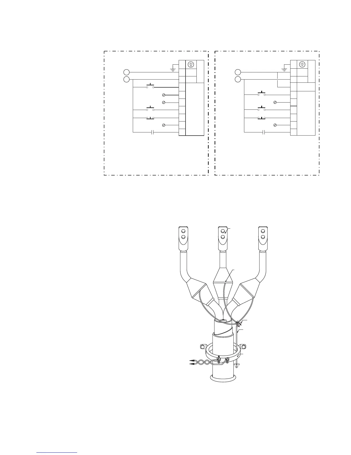
Figure 2-9: CBCT ground CT connection - LO and HI inputs
The exact placement of a zero-sequence CT to detect only ground fault current is shown
below. If the core balance CT is placed over shielded cable, capacitive coupling of phase
current into the cable shield during motor starts may be detected as ground current unless
the shield wire is also passed through the CT window. Twisted-pair cabling on the zero-
sequence CT is recommended.
Figure 2-10: Core balance ground CT installation, shielded cable
M
-
+
A1
A2
A4
A3
A5
A6
A8
A9
A10
A7
+
-
24 VDC CONTACT INPUTS
CONTROL
POWER (VDC)
CONTROL
POWER
24 VDC
FIELD STOP
FIELD START
RESET
M
N
L
A1
A2
A4
A3
A5
A6
A8
A9
A10
L
N
VAC CONTACT INPUTS
CONTROL
POWER (VAC)
CONTROL
POWER
VAC
FIELD STOP
FIELD START
RESET
NR
LO
HI
888742A3.cdr
RETURN
NOTE: AC power and AC input wiring shown.
POWER CABLE
TO MOTOR
TO STARTER
GROUND BUS
CABLE LUGS
TO SOURCE
TERMINATION
(TWISTED PAIR)
SPLIT-BOLT CONNECTOR
888712A1.CDR
CORE BALANCE CT
SECONDARY CONNECTION
TO MM200 IED
IMPORTANT: FOR SHIELDED
CABLE, THE GROUND WIRE
MUST PASS THROUGH THE
CT WINDOW.
50:0.025 CORE BALANCE CT
FOR GROUND SENSING
STRESS CONE
SHIELD GROUND
CONNECTION
BOTTOM OF
MOTOR STARTER
COMPARTMENT

 Loading...


