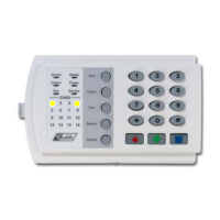
NX-6V2 Control 33
LOC PG DESCRIPTION DEFAULT PROGRAM DATA
29-36 18 RESERVED
L
37 18 SIREN AND SYSTEM SUPERVISION
Segment 1 (Circle Numbers To Program)
1 = Siren sounds for telephone line cut while armed.
2 = Siren sounds for telephone line cut while disarmed.
3 = Siren blast at arming.
4 = Siren blast at exit delay expiration.
5 = Siren blast at closing kissoff.
6 = Siren sounds during a cross-zone verification time.
7 = Siren sounds for a tamper.
8 = Siren blast one time for keyswitch arming, two times for disarming.
(Note: Must be disabled for SIA CP-01
installations.)
Segment 2 (Circle Numbers To Program)
1 = Convert siren driver to voltage out.
2 = Siren sounds for expander trouble (required for U.L.).
3 = Immediate Restore by zone.
4 = Dynamic battery test performed upon arming.
5 = Battery missing test performed every 12 seconds.
6 = Manual bell test performed during [
r
]-[4]-[4] test function.
7 = Manual communicator test performed during [r]-[4]-[4] test function.
8 = Box tamper enabled.
Segment 3 (Circle numbers to program)
1 = Box Tamper report enabled.
2 = AC Fail report enabled.
3 = Low Battery report enabled.
4 = Auxiliary power over current report enabled.
5 = Siren supervision report enabled.
6 = Telephone Line Cut report enabled.
7 = Ground Fault Detection report enabled.
8 = Expander trouble report enabled.
Segment 4 (Circle Numbers To Program)
1 = Failure To Communicate report enabled.
2 = Log Full report enabled.
3 = Autotest report enabled.
4 = Start and End Programming report enabled.
5 = End Download report enabled.
6 = Sensor Low Battery report enabled.
7 = Sensor Missing report enabled.
8 = First to Open / Last to Close.
Segment 5 (Circle numbers to program)
1 = Lost Clock service LED enable.
2 = Zone Doubling enable.
3 = Disable on-board 6 zones.
4 = Enables two trips on the same cross-zone to activate the alarm.
5 = Disables bypass reports for force armed zones
6 = Reserved.
7 = Clock uses internal crystal.
8 = Disable Temporal Siren on Fire (Do not disable on UL listed systems)
Segment 6 (Circle numbers to program)
1 = Enable 2-wire Smoke Detector.
2 = Reserved.
3 = Enable Zone Activity in Hours (not Days)
4 = Enable Daylight Savings Time (DST)
5 = Reserved
6 = Disable Clean Me report
7 = Disable Start/End Test report
8 = Reserved
Segment 7 - RESERVED
L
38 19 SWINGER SHUTDOWN COUNT 1 _
 Loading...
