Wiring the NX-320-I auxiliary power module
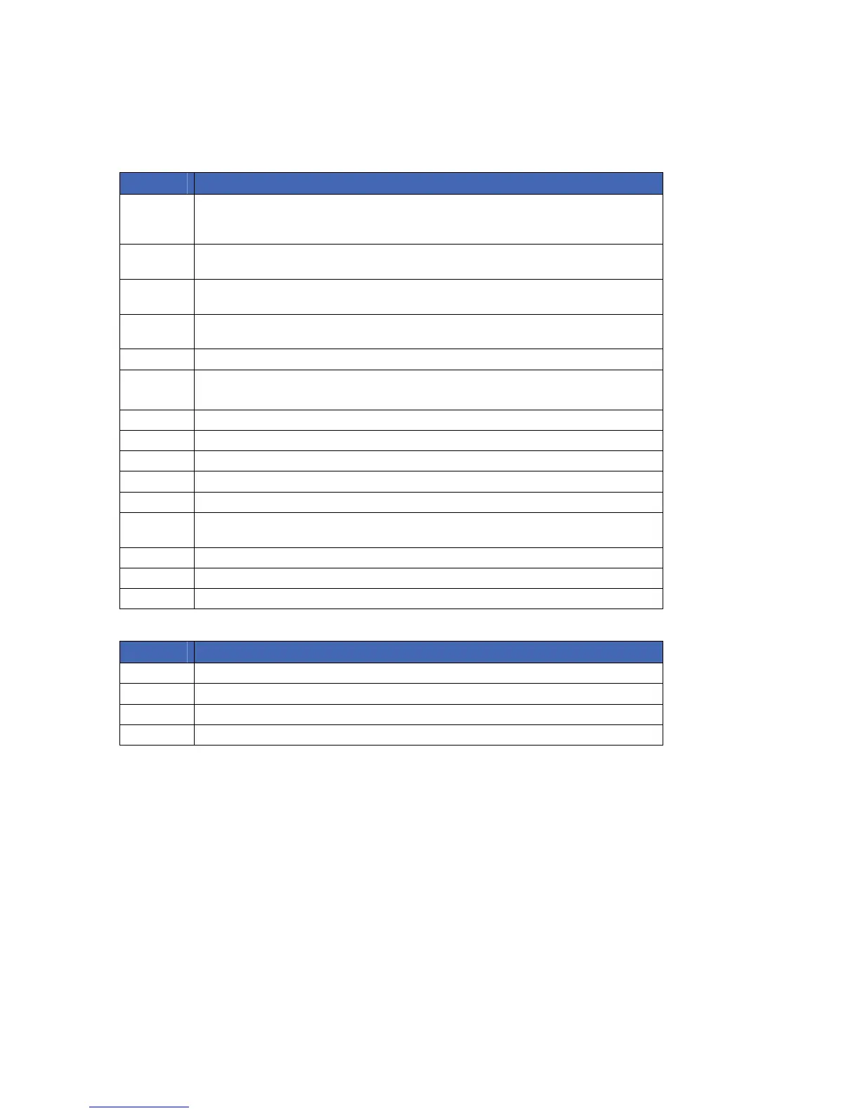
Table 7. NX-320-I auxiliary power module terminal connections
Terminal Description
DATA
Connect to the control panel data terminal. This terminal is the incoming data-signalling
terminal to the NX-320-I. The maximum total wire run from the control panel to all
devices, including the NX-320-I is 800 m.
COM
Connect to the control panel COMMON terminal. This terminal supplies the common side
of the power to the NX-320-I board.
POS
Connect to control panel POS terminal. This terminal supplies power to the NX-320-I
board.
DATA
This terminal is the outgoing data-signalling terminal for buss extension. The maximum
total wire run from the NX-320-I to all outgoing devices is 800 m.
COM Common terminal for any device powered from the NX-320-I.
OUT A Programmable output current limited to 1.5 Amps.
Note: the total current of the NX-320-I is 2.5 Amps.
OUT B Programmable output current limited to 1.5 Amps.
COM Common terminal for any device powered from the NX-320-I.
OUT C Programmable output current limited to 1.5 Amps.
BELL + Positive of bell output current limited to 2.0 Amps.
BELL - Negative of bell output current limited to 2.0 Amps.
TAM
This is an optional tamper terminal. To use this feature, connect the normally closed
tamper switch between this terminal and COM. If switch 4 is off, this feature is not used.
EARTH Earth ground.
AC AC input. Connect to a 16.5 V 40 VA transformer.
AC AC input. Connect to a 16.5 V 40 VA transformer.
LED Description
DS1 Flashes when data is transmitted out from the NX-320-I.
DS2 Flashes when data is transmitted into the NX-320-I.
DS3 Flashes during normal operation.
DS4 Used for hardware, and will only glow dimly when connected to the NX control panel.
Setting the DIP switches
DIP switches 1-3 set the address of the NX-320-I auxiliary power module DIP switch 4 controls the
tamper feature. On enables tamper. Off disables tamper.
 Loading...