A
LED Flashes during normal operation.
B
LED Factory use only.
Note: The printer port present on the board is to be used for service only in an EN certified installation.
Setting the DIP switches
1. Power down the NX-507E/NX-508E output expander.
2. Set the DIP switches according to Table 10. NX-507E/NX-508E output expander DIP
switches.
Note: Switches 1-3 set the module address. DIP switch 4 enables the tamper.
• •If DIP switch 4 is ON, the NX-507E/NX-508E generates a tamper alarm when
the TAM line is unconnected to the COM line.
• •If DIP switch 4 is OFF, the NX-507E/NX-508E does not generate a tamper
alarm if the TAM line is unconnected to the COM line.
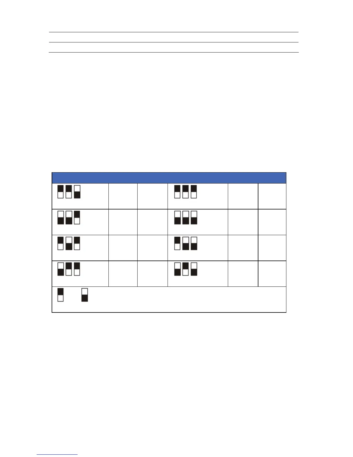
Table 10. NX-507E/NX-508E output expander DIP switches
DIP switch 1-3 settings Address Outputs DIP switch 1-3 settings Address Outputs
24 1-7
28 33-39
25 9-15
29 41-46
26 17-23
30 49-55
27 25-31
31 57-63
= ON = OFF
3. The outputs can be logged in the event log. The output numbers that appear in the event
log are linked to a selected NX-507E/NX-508E output expander address.
4. Power up the NX-507E/NX-508E output expander. The position of all switches is
updated when the NX-507E/NX-508E output expander is powered up.
 Loading...