NX-10 Expander Installation Guide
79
B
4-position DIP
switch
See Table 10. NX-507E/NX-508E output expander DIP switches.
C
LED Flashes during normal operation.
D
LED Factory use only.
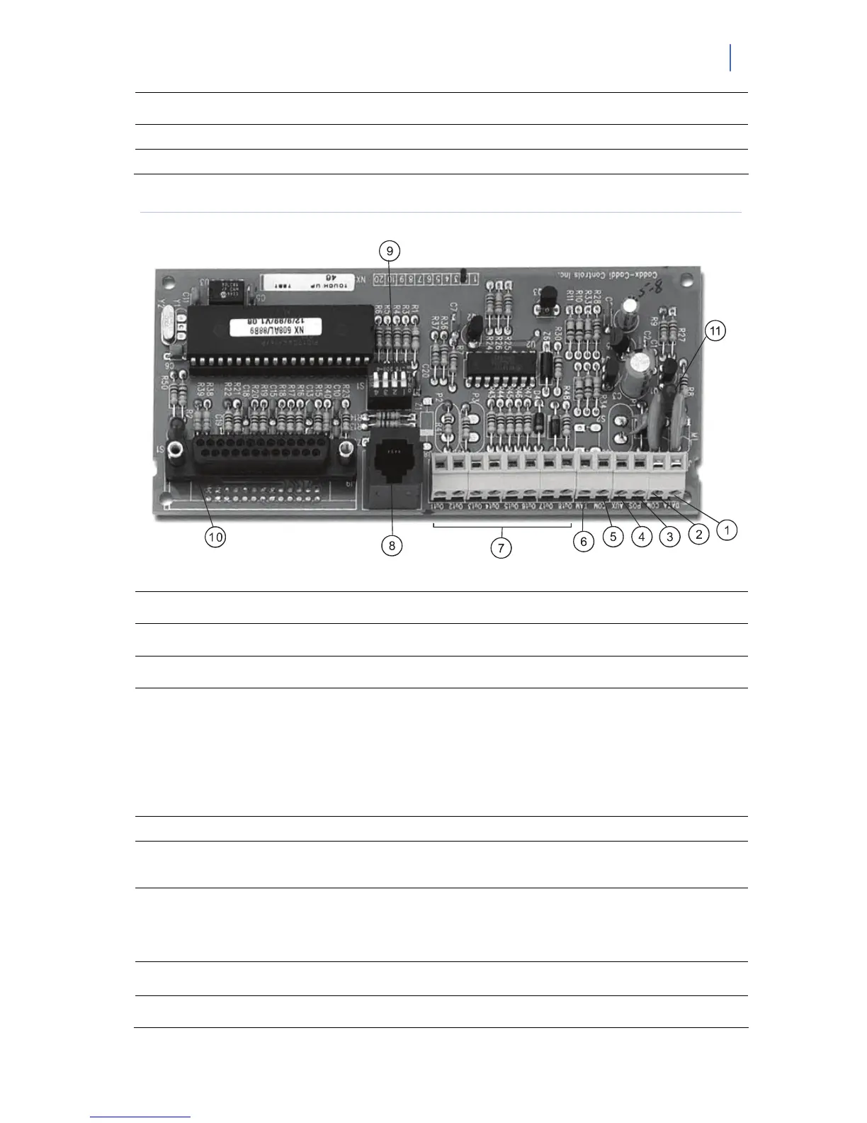
Figure 11. NX-508E output expander
1
DATA Connect to the control panel Data terminal. This terminal is the data-signalling terminal to
all the devices on the bus.
2
COM Connect to the control panel COMMON terminal. This terminal supplies the common side of
he power to the NX-508E board.
3
POS Connect to control panel AUX POWER + terminal. This terminal supplies power to the NX-
508E board.
4
AUX This terminal can supply up to 100 mA fused separate from the power in the control panel.
Note: Any power drain from this terminal should be included in total current draw from the
NetworX control panel or NX-320-I power supply as applicable.
This allows an isolation of the power between the main control and remote devices. If a
short is created past the AUX terminal, those devices will cease to function, but the other
devices, including the NX-508E, will continue to operate. The NX-508E will report this
problem to the control for display on the keypad as an expander power trouble.
5
COM Connect to the tamper terminal through a normally closed contact.
6
TAM This is an option tamper terminal. To use this feature, connect the normally closed tamper
switch between this terminal and COM. If this feature is not used, a jumper must be
connected between this terminal and common (or put DIP 4 to ON).
7
OUT 1-8
Open collector outputs that switch to ground when activated, max. 100 mA.
Note: If device is connected to outputs, it must see the transition from 13V to GND. The
enclosed resistors must be used. Connect the resistor between AUX and the output being
used.
8
X-10 interface
connection point
Only one required per system.
Note: X-10 plug is not to be used in an EN certified installation.
9
4-position DIP
switch
See Table 10. NX-507E/NX-508E output expander DIP switches
 Loading...