Appendix B - Settings and Signals
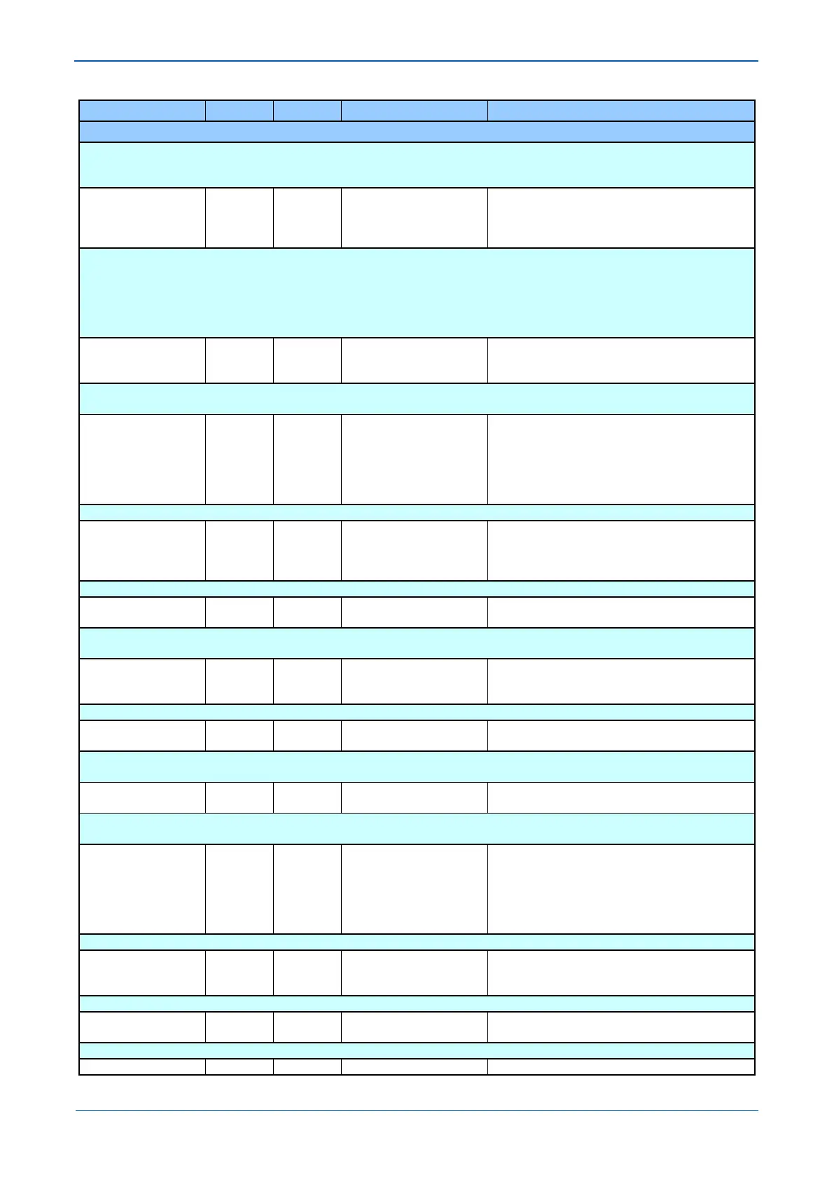
MENU TEXT COL ROW DEFAULT SETTING AVAILABLE OPTIONS
DESCRIPTION
Note: When the ‘Test Mode’ cell is set to ‘Enabled’ the ‘Relay O/P Status’ cell does not show the current status of the output relays and hence
can not be used to confirm operation of the output relays. Therefore it will be necessary to monitor the state of each contact in turn.
Contact Test 0F 0F No Operation
Apply Test
Remove Test
When the ‘Apply Test’ command in this cell is issued the contacts set for operation (set to ‘1’) in the ‘Test Pattern’ cell change state. After the
test has been applied the command text on the LCD will change to ‘No Operation’ and the contacts will remain in the Test State until reset
issuing the ‘Remove Test’ command. The command text on the LCD will again revert to ‘No Operation’ after the ‘Remove Test’ command has
been issued.
Note: When the ‘Test Mode’ cell is set to ‘Enabled’ the ‘Relay O/P Status’ cell does not show the current status of the output relays and hence
can not be used to confirm operation of the output relays. Therefore it will be necessary to monitor the state of each contact in turn.
Test LEDs 0F 10 No Operation
Apply Test
When the ‘Apply Test’ command in this cell is issued, the eighteen user-programmable LEDs will illuminate for approximately 2 seconds
before they extinguish and the command text on the LCD reverts to ‘No Operation’.
Test Autoreclose 0F 11 No Operation
Trip 3 Pole
Trip Pole A
Trip Pole B
Trip Pole C
This is a command used to simulate a single or three pole tripping in order to test Auto-reclose cycle.
Loopback Mode 0F 13 Disabled
External
Internal
Setting that allows communication loopback testing.
IM64 TestPattern 0F 14 0
From 0 to 16 in steps of 1
[Binary Flag (16)]
This cell is used to set the DDB signals included in the User Defined Inter-IED Commands IM64 when the ‘IM64 Test Mode’ cell is set to
‘Enable’.
IM64 Test Mode 0F 15 Disabled
Enabled
When the Enable command in this cell is issued the DDB set for operation (set to ‘1’) in the ‘Test Pattern’ cell change state.
Red LED Status 0F 1A
Red LED Status
[Binary Flag (18)]
This cell is an eighteen bit binary string that indicates which of the user-programmable LEDs on the IED are illuminated with the Red LED
input active when accessing the IED from a remote location, a ‘1’ indicating a particular LED is lit and a ‘0’ not lit.
Green LED Status 0F 1B
Green LED Status
[Binary Flag (18)]
This cell is an eighteen bit binary string that indicates which of the user-programmable LEDs on the IED are illuminated with the Green LED
input active when accessing the IED from a remote location, a ‘1’ indicating a particular LED is lit and a ‘0’ not lit.
IED Mod/Beh 0F 1E
On-blocked
Test
Test-blocked
Off
Indicates the current Mod/Beh status of whole IED
Subscriber Sim 0F 1F Disabled
Enabled
Used to enable/disable the 'subscriber simulation' feature, for Sampled Values and GOOSE subscriptions
DDB 31 - 0 0F 20
DDB 31 - 0
[Binary Flag (32)]
Displays the status of DDB signals
 Loading...


