Appendix B - Settings and Signals
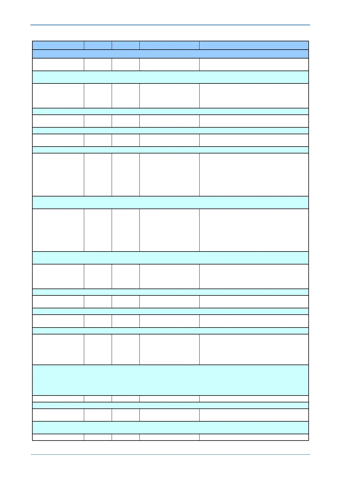
MENU TEXT COL ROW DEFAULT SETTING AVAILABLE OPTIONS
DESCRIPTION
En VTSandCh Fail
[Indexed String]
Setting that defines third stage overcurrent operating status. Depending of this setting, IN>3 will be enabled permanently or in case of
Voltage Transformer Supervision (fuse fail) operation, or in case of communication channel fail, or a combination (and /or) of both.
IN>3 Directional 38 47 Directional Fwd
Directional Fwd
Directional Rev
This setting determines the direction of measurement for the earth fault overcurrent element.
IN>3 Current Set 38 4A 10
From 0.08*I1 to 32*I1 in steps of 0.01*I1
[Courier Number (current)]
Pick-up setting for third stage earth fault overcurrent element.
IN>3 Time Delay 38 4B 0
From 0 to 200 in steps of 0.01
[Courier Number (time-seconds)]
Setting for the operating time-delay for third stage earth fault overcurrent element.
IN>4 Status 38 4D Disabled
Enabled
Enabled VTS
Enabled Ch Fail
En VTSorCh Fail
En VTSandCh Fail
Setting that defines fourth stage overcurrent operating status. Depending of this setting, IN>4 will be enabled permanently or in case of
Voltage Transformer Supervision (fuse fail) operation
IN>4 Status 38 4D Disabled
Enabled
Enabled VTS
Enabled Ch Fail
En VTSorCh Fail
En VTSandCh Fail
Setting that defines fourth stage overcurrent operating status. Depending of this setting, IN>4 will be enabled permanently or in case of
Voltage Transformer Supervision (fuse fail) operation, or in case of communication channel fail, or a combination (and /or) of both.
IN>4 Directional 38 4E Non-Directional
Directional Fwd
Directional Rev
This setting determines the direction of measurement for the earth fault overcurrent element.
IN>4 Current Set 38 51 10
From 0.08*I1 to 32*I1 in steps of 0.01*I1
[Courier Number (current)]
Pick-up setting for fourth stage earth fault overcurrent element.
IN>4 Time Delay 38 52 0
From 0 to 200 in steps of 0.01
[Courier Number (time-seconds)]
Setting for the operating time-delay for fourth stage earth fault overcurrent element.
IN> Blocking 38 54 0x00F
VTS Blocks IN>2
VTS Blocks IN>3
VTS Blocks IN>4
Logic Settings that determine whether blocking signals from VT supervision affect certain earth fault overcurrent stages.
VTS Block - only affects directional earth fault overcurrent protection. With the relevant bit set to 1, operation of the Voltage Transformer
Supervision (VTS), will block the stage. When set to 0, the stage will revert to Non-directional upon operation of the VTS.
If IN> Status is set ‘Enabled VTS’, no blocking should be selected in order to provide earth fault clearance by earth fault overcurrent
protection during VTS condition.
Earth Fault Directional Sub Heading
IN> Char Angle 38 56 -60
From -95 to 95 in steps of 1
[Courier Number (angle)]
Setting for the IED characteristic angle used for the directional decision. The setting is visible only when ‘Directional Fwd’ or ‘Directional Rev’
is set.