Appendix B - Settings and Signals
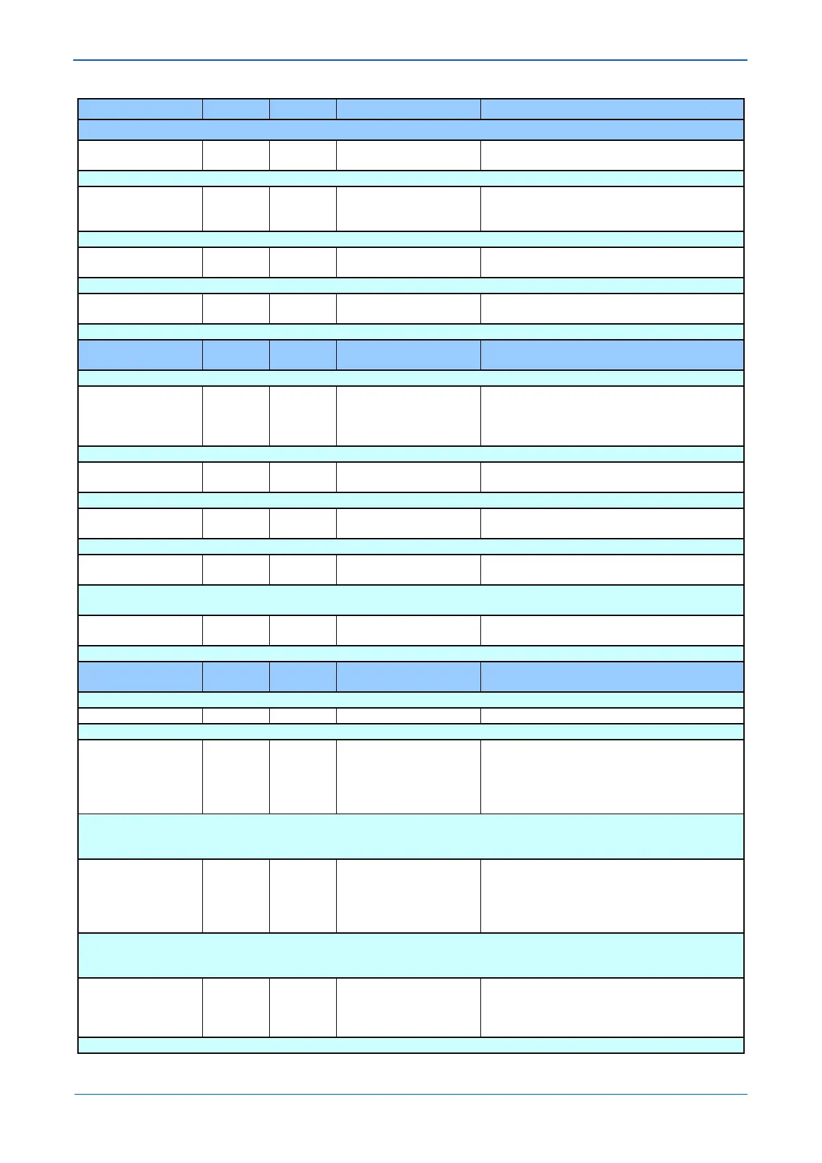
MENU TEXT COL ROW DEFAULT SETTING AVAILABLE OPTIONS
DESCRIPTION
VN>1 tReset 3B 06 0
From 0 to 100 in steps of 0.01
[Courier Number (time-seconds)]
Setting to determine the reset/release definite time for the first stage characteristic
VN>2 Status 3B 07 Disabled
Enabled
Setting to enable or disable the second stage definite time residual overvoltage element.
VN>2 Voltage Set 3B 08 10
From 1*V1 to 80*V1 in steps of 1*V1
[Courier Number (voltage)]
Pick-up setting for the second stage residual overvoltage element.
VN>2 Time Delay 3B 09 10
From 0 to 100 in steps of 0.01
[Courier Number (time-seconds)]
Operating time delay for the second stage residual overvoltage element.
GROUP 1: THERMAL
OVERLOAD
3C 00
This column contains settings for Thermal Overload
Characteristic 3C 01 Single
Single
Dual
Setting for the operating characteristic of the thermal overload element.
Thermal Trip 3C 02 1
From 0.08*I1 to 4.0*I1 in steps of 0.01*I1
[Courier Number (current)]
Sets the maximum full load current allowed and the pick-up threshold of the thermal characteristic.
Thermal Alarm 3C 03 70
From 50 to 100 in steps of 1
[Courier Number (percentage)]
Setting for the thermal state threshold corresponding to a percentage of the trip threshold at which an alarm will be generated.
Time Constant 1 3C 04 10
From 1 to 200 in steps of 1
[Courier Number (time-minutes)]
Setting for the thermal time constant for a single time constant characteristic or the first time constant for the dual time constant
characteristic.
Time Constant 2 3C 05 5
From 1 to 200 in steps of 1
[Courier Number (time-minutes)]
Setting for the second thermal time constant for the dual time constant characteristic.
42 00
This column contains settings for Voltage protection
Under Voltage Sub Heading
V< Measur't Mode 42 02 V<1 & V<2 Ph-Ph
V<1 & V<2 Ph-N
V<1Ph-Ph V<2Ph-N
V<1Ph-N V<2Ph-Ph
Sets the combination of measured input voltage that will be used for the undervoltage elements.
Note: If any stage is disabled, the associated text in the setting menu cell setting will remain visible but will not affect the operation of the
V< Operate Mode 42 03 V<1 & V<2 Any Ph
V<1 & V<2 3 Phase
V<1AnyPh V<2 3Ph
V<1 3Ph V<2AnyPh
Setting that determines whether any phase or all three phases has to satisfy the undervoltage criteria before a decision is made.
Note: If any stage is disabled, the associated text in the setting menu cell setting will remain visible but will not affect the operation of the
V<1 Function 42 04 DT
DT
IDMT
Setting for the tripping characteristic of the first stage undervoltage element.